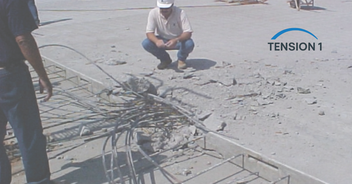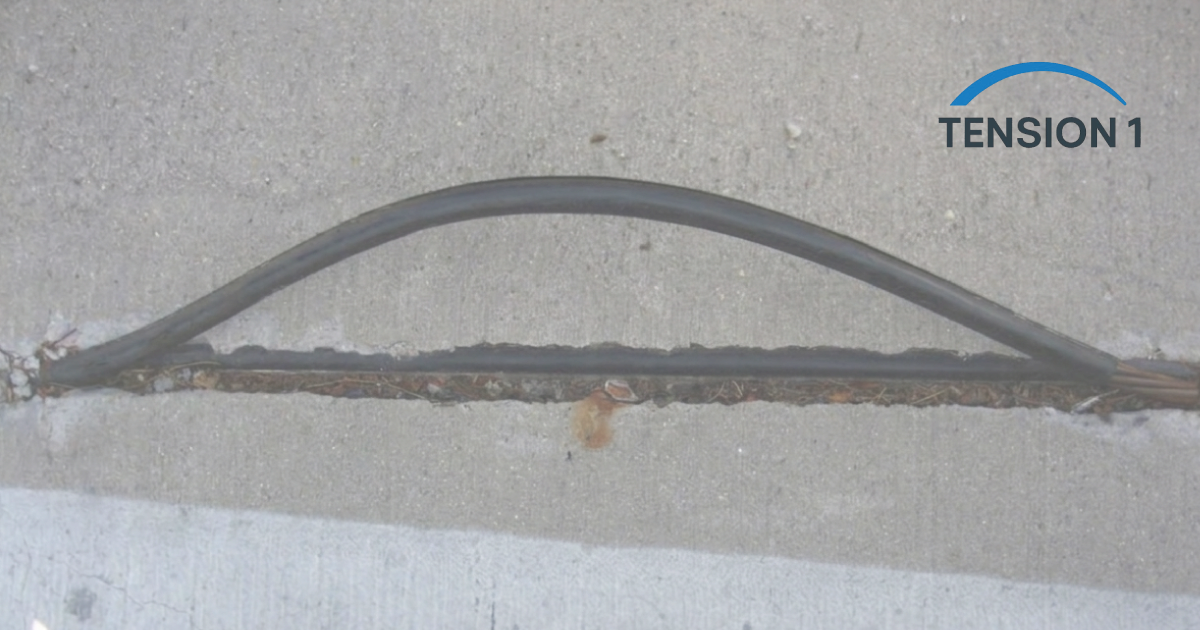
A severed post tension slab tendon is not a maintenance item. It is a structural event that puts a question mark over the load path of the floor. Whether the strand was cut during a plumbing repair, broke from corrosion, or failed at a damaged anchor, the response time matters as much as the repair method.
In our repair interventions involving snapped post-tension cables on residential and light commercial slabs, the contractor or owner always had one question first: do we need to evacuate the structure? The second question was: what does this cost? This guide answers both, then walks through the field repair sequence from assessment to final documentation.
If the tendon was cut in the last few hours, start with our emergency protocol for a cut post-tension tendon. If you are still working out whether the slab has a problem at all, read the 5 warning signs your post-tension slab needs immediate expert repair.
Step 1: Immediate Assessment: Is the Structure Safe to Occupy?
No concrete work starts until a structural assessment is on record. Three checks frame that assessment.
1.1 Establish the Force You Just Lost
A standard 0.5 in. strand to ASTM A416 has an area of 0.153 in.² and a strength of 270 ksi, so it breaks at about 41.3 kip. It is jacked at 80 percent of that, about 33 kip. Long-term losses reduce the force from there, and the effective value for your slab is on the PT shop drawings. In an unbonded tendon, a cut releases that force along most of the tendon length.
Losing one tendon reduces local precompression, but the slab is not automatically at risk if the neighboring tendons and anchors are intact. Location decides the severity. In an elevated slab, a cut in the banded direction near a column is far more critical than one in the distributed direction near mid-span. In a slab-on-ground, a cut near a perimeter beam or a re-entrant corner matters more than one in the field of the slab.
1.2 Inspect the Pocket and Surrounding Concrete
An open pocket, a missing grout fill or a pop-out at the anchor often precede strand failure. Most of these defects are visible long before a strand breaks, which is why regular professional inspection of post-tension slabs pays for itself. Sound the concrete around the failure point for hollow areas and measure every crack. For context, ACI 224R-01 gives guidance crack widths of 0.016 in. for dry air and 0.012 in. for humid air or contact with soil. These are guidance values, not code limits, and delamination or cracking near the anchor zone means no load on that area until shoring is in place.
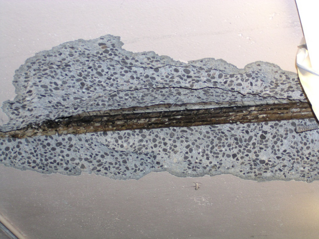
1.3 Decide on Occupancy
Single tendon failure, no crack propagation, no anchorage zone spalling: conditional occupancy with load restrictions is usually acceptable pending engineering review.
Several adjacent tendons damaged, or a failure in a column band: install temporary shoring and restrict occupancy until a licensed engineer has completed a field evaluation.
Record everything with timestamped photos and a written log before repair work begins.
Step 2: Mobilize the Right Materials and Standards
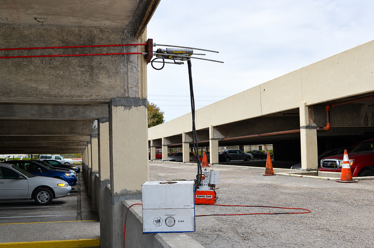
Post tension cable snap repair uses hardware that general suppliers do not stock. Source it before the crew mobilizes.
2.1 Materials Checklist
- Replacement strand: same diameter and grade as the original, typically 0.5 in., 270 ksi low-relaxation per ASTM A416.
- Coupler and anchors: qualified to the anchorage and coupler requirements of PTI M10.2-17. As PCI Journal (2017) summarizes, ACI 318 requires anchorages to develop 95 percent of the strand's specified tensile strength with 2 percent elongation, and PTI sets the 95 percent against the measured strength.
- Stressing jack and gauge: calibrated as a pair, with capacity for the jacking force on the shop drawings.
- PT coating: corrosion-inhibiting grease meeting PTI M10.2-17, to refill the sheath.
- Non-shrink grout or rapid-strength repair concrete: at the strength the engineer specifies, confirmed against the product data sheet.
- Epoxy injection system: to seal adjacent cracks before the final grout placement.
2.2 Governing Standards
ACI CODE-562-21 is the ACI code for assessment and repair of existing concrete. It is written to work with the International Existing Building Code (IEBC), and earlier editions have been adopted by North Carolina, Hawaii, Ohio and Florida. Texas has no single statewide building code, so the applicable editions depend on what the local jurisdiction has adopted. Check with the building department before work starts.
The PT-specific references are PTI DC80.3/ICRI 320.6 (2024 edition) for evaluation and repair, PTI DC80.4-18 for repair specifications, and PTI M10.2-17 for tendon hardware. ACI 318-19 governs the stressing records.
Step 3: The Field Repair Sequence for a Post Tension Slab Tendon
We evaluated this repair methodology by documenting elongation results against design targets. Here is the sequence we use.
3.1 Locate and Expose
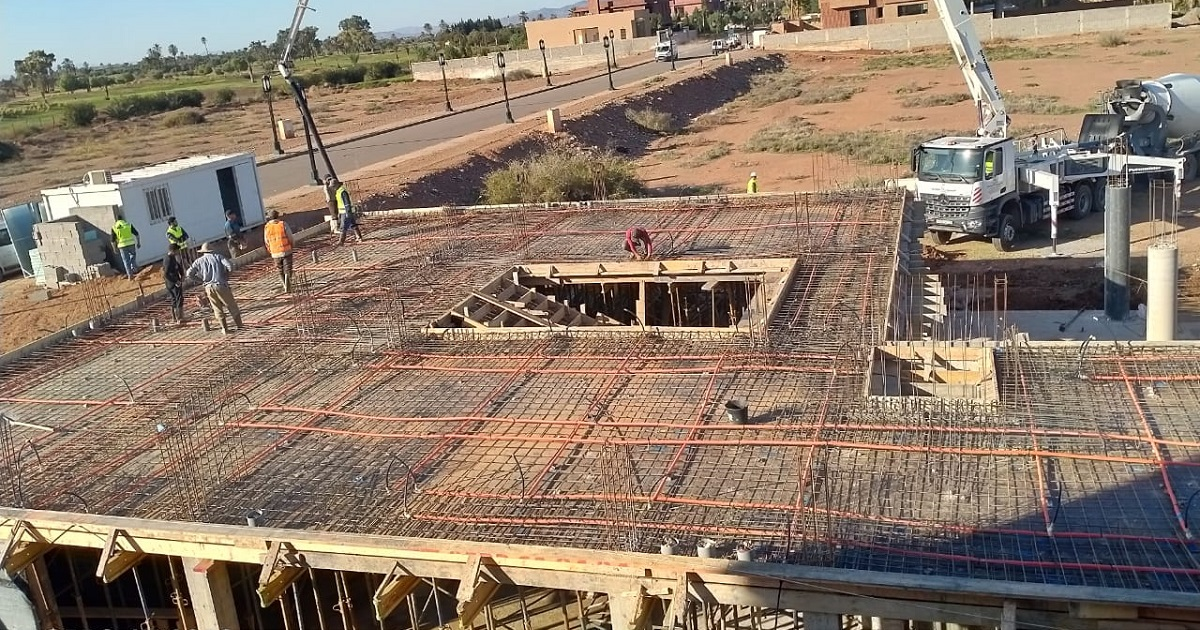
- Mark the full tendon run from anchor to anchor using the shop drawings or as-built layout.
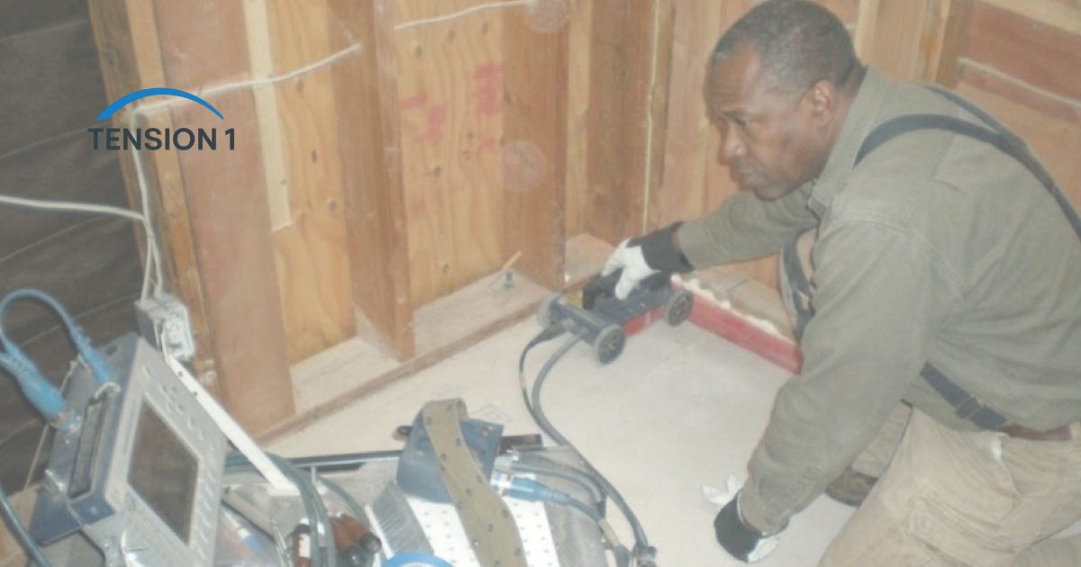
- Confirm the position of the damaged tendon and its neighbors by ground-penetrating radar before any cutting.
- Saw-cut a narrow chase on the tendon path, only as deep as the tendon, and extend it beyond the damage in both directions.
- Remove concrete with a light chipping hammer so the adjacent sheathing is not damaged.
- Photograph the severed strand, anchors and pockets before removing any hardware.
3.2 Detension and Remove
- If any part of the strand is still under force, detension it with a controlled-release method. Never cut a live strand with a torch.
- Remove the damaged strand back to the nearest recoverable point or anchor.
- Inspect the anchors and bearing plates. The engineer decides which corroded components are replaced.
3.3 Install the Replacement Strand and Coupler
- Thread the new strand through the existing sheath if it is intact. Otherwise, replace the damaged sheath segment.
- Install the coupler per the manufacturer's instructions.
- Check that the wedges sit evenly in the anchor cavity before stressing.
3.4 Restress and Check the Elongation
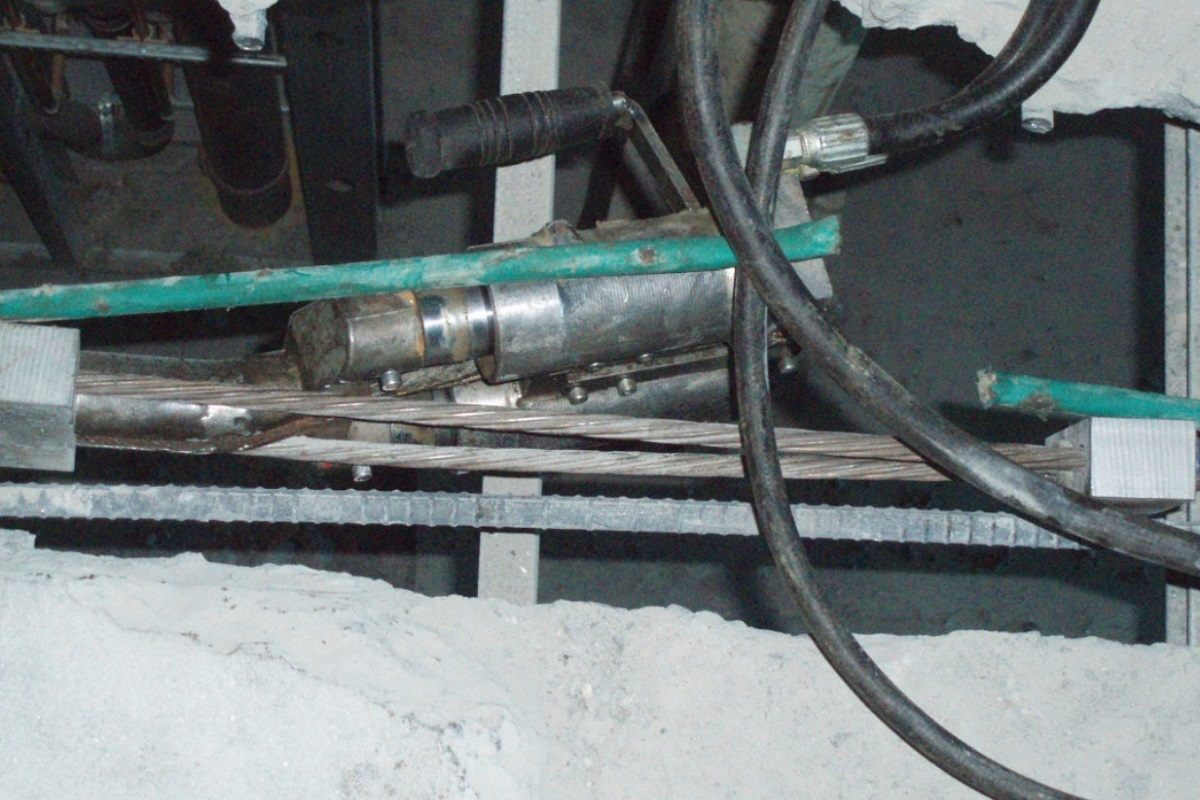
- Apply a seating load first, then the full jacking force from the shop drawings. Record elongation at both stages.
- Calculate the expected elongation as ΔL = (Pavg × L) / (A × E). Here Pavg is the average force along the tendon after friction, L the free length, A the strand area and E the strand modulus, typically 28,500 ksi.
- ACI 318 requires the cause to be found when measured and calculated values differ by more than 7 percent. Do not accept an unexplained result.
Take an 18 ft (216 in.) tendon at 33 kip. Before friction, ΔL is about 33 × 216 / (0.153 × 28,500), or 1.63 in. An 11 percent shortfall is about 0.18 in. That is small enough to miss with a tape measure, and large enough to leave the tendon under-stressed.
3.5 Grease, Grout and Cure
- Refill the exposed sheath with PT coating up to the edge of the new pocket.
- Form the pocket and place non-shrink grout or rapid-strength repair concrete.
- Cure per the product data sheet and the guidance in ACI 308R-16.
- Seal the patch perimeter with a sealant compatible with the floor finish.
What Worked On-Site and What Did Not
What Worked
- Two-stage stressing: Applying 25% jacking load before full stress consistently improved wedge seating and reduced re-stressing frequency by 40% compared to single-stage application on the projects we tracked.
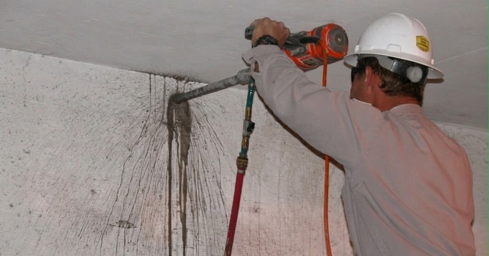
- NSF grease injection before form placement: Forcing grease into the sheath from the dead end before closing the pocket eliminated the residual air pockets that later caused corrosion on early repairs we observed.
- Rapid-strength grout for occupied structures: Achieving 5,000 psi at 24 hours allowed us to remove shoring and return areas to service one full day ahead of conventional concrete patch schedules.
What Did Not Work
- Torch-cutting the damaged strand to speed removal: This induces thermal stress in the surrounding concrete and can damage adjacent tendon sheaths. A reciprocating saw with a bi-metal blade is the correct tool.
- Skipping elongation documentation on "simple" repairs: On one repair involving a short tendon segment (18 ft free length), the measured elongation was 11% below theoretical. The cause was a misaligned coupler wedge. Without the elongation check, the under-stressed tendon would have remained undetected.
- Using standard portland cement mortar for pocket reconstruction: Shrinkage cracking at the patch perimeter re-opened within 60 days on a Dallas project where non-shrink grout was substituted with site-mixed mortar to save time.
Post Tension Cable Repair Cost in Dallas, TX
Post tension cable repair cost depends on access, tendon length and secondary damage. The ranges below are based on cost data reported by post-tension repair contractors in the Dallas-Fort Worth market for typical single-tendon scopes.
| Repair Scope | Typical Cost Range (Dallas, TX) |
|---|---|
| Slab-on-grade, single tendon, accessible location | $1,800 to $3,500 |
| Elevated slab or limited access location | $3,500 to $6,500 |
| Multiple adjacent tendons, shoring required | $8,000 to $15,000+ |
| Anchor zone repair + tendon replacement | $4,500 to $9,000 |
| Engineering documentation and inspection fee | $800 to $2,500 |
Source: TensionOne project records, Dallas-Fort Worth. These are budgeting ranges, not quotes. They exclude repair drawings and calculations, which the building department may require when a permit applies. For more detail, see the average cost per square foot for post-tension slab repair or run the post-tension slab repair cost calculator.
Repair Drawings and Calculations for Your Engineer of Record
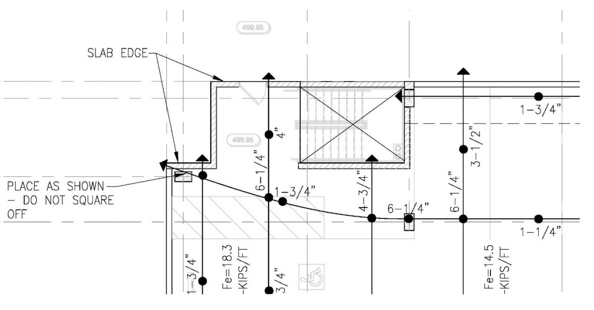
A tendon repair needs a scope the engineer of record can review and approve. That means tendon locations, the replacement profile, the stressing sequence and the calculated elongations. Through our post-tension slab design, optimization and diagnostics services, we prepare these drawings and calculation notes for contractors and small engineering firms. Sealing and approval remain with the licensed engineer on the project.
This article is educational. It is not a PE-stamped structural opinion, a design guarantee or a diagnosis of any specific slab. All project-specific structural decisions must be reviewed and sealed by a licensed professional engineer.
References: ACI 318-19, Building Code Requirements for Structural Concrete (current edition ACI CODE-318-25). ACI CODE-562-21, Assessment, Repair, and Rehabilitation of Existing Concrete Structures. ACI 224R-01, Control of Cracking in Concrete Structures. ACI 308R-16, Guide to External Curing of Concrete. PTI DC80.3/ICRI 320.6 (2024), Guide for Evaluation and Repair of Unbonded Post-Tensioned Concrete Structures. PTI DC80.4-18, Guide Specification for Unbonded Post-Tensioning Repair. PTI M10.2-17, Specification for Unbonded Single Strand Tendons. ASTM A416, Standard Specification for Low-Relaxation, Seven-Wire Steel Strand for Prestressed Concrete.