Estimated reading time: 7 minutes  |  Article type: Cluster Page  |  Author: Joseph, Civil Engineer & Founder, TensionOne LLC

Why a Single Saw Cut Can Trigger a Structural Emergency

A post-tension slab is not a conventional concrete floor. Embedded within it are high-strength steel tendons stressed to forces typically ranging from 25 to 33 kips per strand. That prestress force is what controls crack width, governs deflection, and keeps the slab performing across its design life. When a contractor or homeowner cuts into that slab without understanding what lies beneath, the risk is not cosmetic damage — it is the sudden, violent release of stored energy that can snap a tendon and propagate a crack through the entire floor.

A plumber routing a new drain line. A homeowner adding a floor drain. An electrician cutting a conduit trench. In each case, the physical consequence of severing an unbonded PT tendon ranges from a localized pop-out to a crack running 20 ft or more across the slab.

The five mistakes documented in this article are the most common failure points we observe in the field when working on post-tension slab projects across Texas. Understanding these errors — and the code provisions that govern them — is the first line of defense before any concrete cutting operation begins.

Code Reference

ACI 318-19 Section 26.6.2 requires that post-tensioning tendon locations be documented as part of the construction record. PTI DC80.3 (Specification for Unbonded Single Strand Tendons) provides the standard for tendon fabrication, installation, and stressing.

Mistake #1

Skipping a Ground-Penetrating Radar Scan Before Any Cut

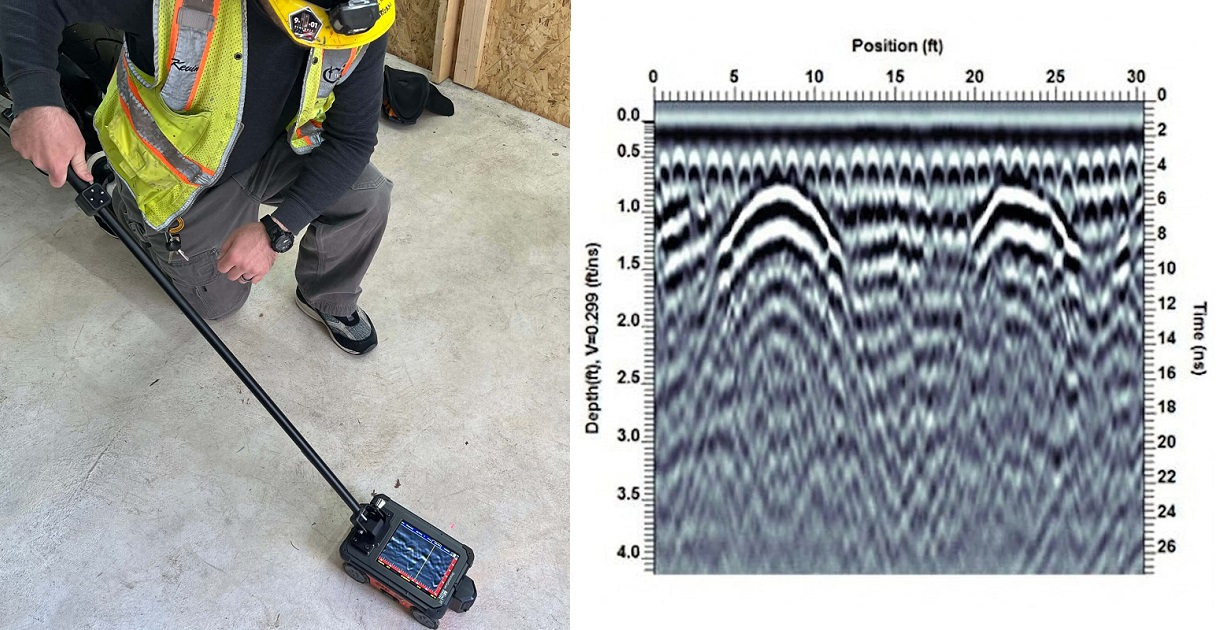
A technician using a GPR scanner on a concrete slab alongside a digital radargram showing hyperbolic reflections of embedded post-tension cables and rebar.
Ground Penetrating Radar (GPR) allows engineers to "see" inside the concrete, identifying the exact location and depth of tendons before any drilling or cutting begins.

This is the most consistent error we encounter, and it carries the most immediate consequences. Many contractors assume they can estimate tendon position from the original construction drawings or from a rough knowledge of typical PT layouts. On a standard residential slab in Texas, unbonded monostrand tendons are typically banded in one direction and distributed at roughly 5-ft spacing in the other — but that is the design intent, not a guarantee of final placement.

During installation, tendons shift. A tendon specified at 5 ft on center can sit at 4.2 ft or 5.8 ft after placement, particularly around blockouts, post locations, or areas where the installer adjusted the profile to clear plumbing rough-ins. No drawing captures final as-built position with the precision required for a safe saw cut.

Ground-penetrating radar (GPR) scanning, performed by a qualified technician with a calibrated 1.6 GHz or 2.0 GHz antenna, resolves tendon location to within approximately +/- 0.5 in at slab depths typical of residential construction (3.5 in to 5 in clear cover). Before any core drill, saw cut, or mechanical penetration, a GPR scan is the non-negotiable first step.

What Worked On-Site

  • GPR accurately locates unbonded tendons and mild steel in a single pass
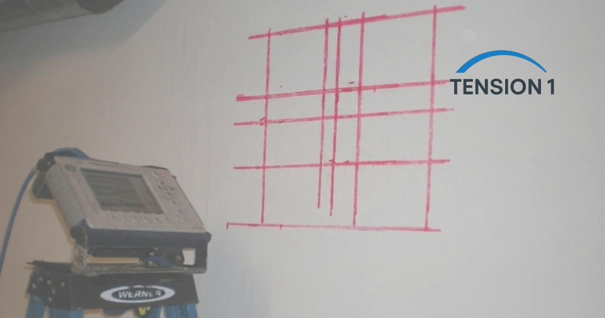
  • Results can be marked directly on the slab surface with chalk or paint
  • Non-destructive — no damage to the existing structure

What Did Not Work

  • GPR does not reliably distinguish a tendon from rebar in congested zones without experienced interpretation
  • Scan quality degrades over slabs with dense metallic topping or thick topping concrete
  • Requires a qualified technician — not a DIY operation
Field Note

For a residential slab cutting project, for example in a Dallas-area home built in the late 1990s, GPR scanning has been shown to shift proposed cut lines by as much as 8 in from positions estimated using original permit drawings. That gap is the difference between a clean utility penetration and a severed tendon.

Mistake #2

Failing to Identify the Tendon Anchorage Zone Before Cutting

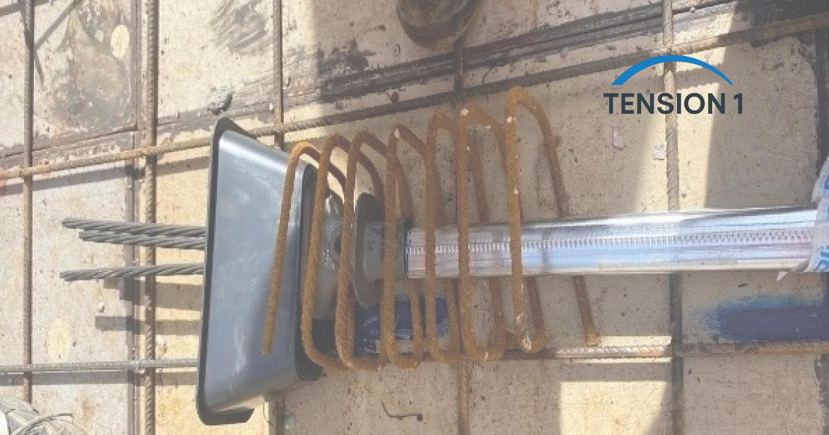
The anchorage zone is the area at each slab edge where the tendon terminates in a cast-in anchor pocket. It is structurally the most critical zone in the entire post-tension slab system. Within approximately 18 in of the slab perimeter at anchorage locations, the local concrete is under high bearing stress and contains the dead-end anchor or the stressed-end chuck assembly.

Cutting through this zone — even with a GPR scan in hand — can fracture the anchorage concrete, displace the bearing plate, or cut into the tail of the tendon just past the anchor. Any of these outcomes releases the prestress in that strand and eliminates the contribution of that tendon to the overall force balance.

PTI DC80.3 specifies minimum edge distances and concrete strength requirements at anchorage zones. ACI 318-19 Section 25.8 addresses development and anchorage of post-tensioning tendons in terms of the structural adequacy of the zone. Before establishing a cut line, contractors must locate all anchorage pockets on the perimeter — typically visible as small rectangular patches in the slab edge — and establish a no-cut buffer zone around each one.

Design Note

A competent PT slab package includes an anchorage zone layout drawing showing pocket locations, tendon direction, and live-end versus dead-end designations. If that drawing is unavailable, do not proceed with cutting near perimeter edges without engineering review. [VERIFY: Confirm minimum edge buffer requirements per PTI DC80.3 Table X for the specific tendon system in use]

Mistake #3

Cutting Across the Banded Direction Without Calculating Force Redistribution

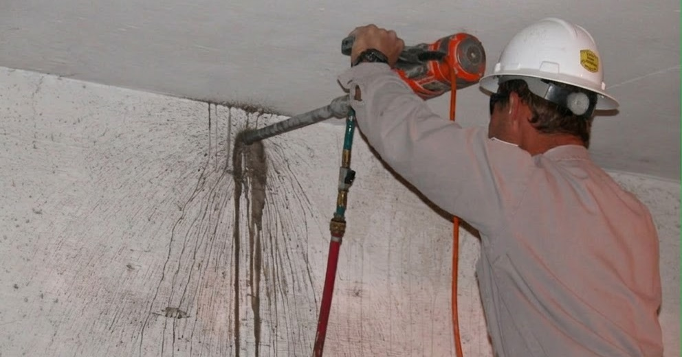
A construction worker wearing a hard hat drills into a concrete ceiling near a wall junction, demonstrating the high risk of hitting tendons in a post tension slab.
Unplanned drilling or coring into a post tension slab can accidentally sever structural cables, requiring immediate and expensive specialized repairs.

A standard residential PT slab in Texas uses an unbonded monostrand layout with tendons banded in one plan direction (typically parallel to the long dimension of the slab) and distributed at even spacing in the perpendicular direction. The banded direction concentrates multiple tendons — often 3 to 6 strands — within a narrow 24-in to 36-in band at column lines.

Cutting a linear trench or a large-diameter core through that banded zone severs multiple tendons at once. Even severing one tendon in a banded group changes the moment distribution along the column strip. Severing two or more significantly reduces the capacity of that strip and can push serviceability checks — deflection, cracking — well beyond ACI 318-19 limits.

The correct approach is to route all new penetrations through the distributed (non-banded) direction, in the mid-panel zone where tendon spacing is at its maximum. Before any penetration in or near a banded zone, a structural engineer must evaluate the residual moment capacity of the affected cross-section. This is not a field judgment call. For more background on how PT slab systems carry load compared to conventional reinforced concrete, see our detailed overview on post-tension vs. reinforced concrete slab design.

Mistake #4

Cutting Without a Stressing and Repair Protocol in Place

Even when a cut is performed correctly and GPR confirms no tendon is directly in the cut path, the structural engineer of record must have reviewed and approved the penetration before work begins. Beyond approval, a repair protocol should be in place for the one scenario that field work inevitably encounters: what happens if a tendon is nicked, damaged, or unexpectedly severed during cutting?

We have seen projects where a tendon was partially cut — not fully severed — because the saw blade grazed the outer HDPE sheathing of an unbonded monostrand. In an unbonded system, the prestressing strand is fully encased in a grease-filled HDPE duct. A nick in the sheathing allows moisture ingress, initiating a corrosion process that is invisible from the surface and can compromise the tendon over a period of years.

A proper repair protocol for unbonded PT systems includes: (1) exposing the full length of the damaged zone, (2) cutting and removing the compromised segment, (3) splicing using a PTI-approved coupler and re-stressing from the nearest accessible end, and (4) sealing the repair with a corrosion-inhibiting grease and re-encasing in new HDPE. This process requires a certified PT installer and documented elongation verification.

Protocol Reminder

ACI 318-19 Commentary R26.10.2 discusses the importance of tendon repair documentation. PTI DC80.3 Section 9 covers repair procedures for damaged unbonded tendons. Any repair involving re-stressing must be logged and included in the project as-built records.

If you are evaluating whether PT is the right system for an upcoming project — or weighing the long-term maintenance implications versus conventional rebar construction — our analysis on post-tension vs. rebar for residential construction and the ROI of post-tension slabs provides a direct performance and cost breakdown.

Mistake #5

Relying on the Original Construction Drawings as the Sole Layout Reference

This mistake is subtler than the others, and it catches experienced contractors off guard precisely because they believe they are doing the right thing. Pulling the original permit drawings and working from the tendon layout plan is better than nothing — but it is not a substitute for field verification.

Original PT drawings represent design intent at the time of permit submission. They do not capture field changes made during installation: tendons rerouted around plumbing rough-ins, profiles adjusted to clear form stakes, or areas where the installer substituted a banded layout for a distributed one because of a last-minute column relocation. In Texas, where residential PT slabs are poured rapidly, these field deviations are common and frequently undocumented.

Additionally, drawings produced decades ago may use coordinate systems referenced to column lines that no longer correspond to identifiable physical features in a remodeled interior. A 5-ft dimension from a column centerline on a 1988 drawing is not reliably locatable in a room where partitions have been moved and the column is now buried in a wall.

The only defensible workflow is: obtain original drawings, use them to inform the GPR scan targeting strategy, perform the scan, reconcile scan results against drawing predictions, and document any discrepancies. This is also directly relevant to the broader question of when a post-tension slab is the right structural choice — the system provides exceptional long-term performance when properly documented and maintained.

The Structural Logic Behind These Cautions: How Post-Tension Slabs Actually Work

Understanding why these mistakes are dangerous requires a clear picture of how a post-tension slab carries load. Unlike a conventionally reinforced slab, where mild steel bars resist tensile stress passively after the concrete cracks, a PT slab uses active prestress to counteract a portion of the applied loads before any cracking occurs.

The tendons are stressed to a specified elongation — typically verified against a calculated target value using the force-elongation relationship for the specific strand system. That elongation check is the primary field verification that the correct prestress force has been applied. Once stressed and anchored, each tendon exerts a continuous upward balanced load on the slab equal to the tendon force multiplied by the curvature of its profile.

This balanced load reduces the net gravity load that the concrete section must carry in flexure. ACI 318-19 Section 8.3.4.1 permits an average minimum prestress of 125 psi for two-way PT slabs without bonded reinforcement. That value establishes the lower bound of structural performance. A slab operating near that minimum has limited reserve capacity to absorb the loss of even one or two tendons.

For a complete breakdown of how this structural logic affects the comparison with conventionally reinforced systems in high-rise and commercial projects, our articles on PT vs. RC slab efficiency for high-rise construction and PT vs. rebar cost and performance for commercial builders provide the structural and financial framework.

A Practical Pre-Cut Checklist for Contractors and Field Engineers

We evaluate penetration requests through a structured review sequence before any physical work is authorized. The following checklist reflects that sequence and is applicable to any residential or light commercial post-tension slab penetration in Texas.

  1. Obtain all available original PT drawings, including tendon layout plans, stressing schedules, and any as-built markups.
  2. Commission a GPR scan by a certified technician. Specify a 1.6 GHz or 2.0 GHz antenna for standard residential slab depths. Request a marked-up slab plan showing all detected anomalies.
  3. Reconcile GPR scan results against original drawing predictions. Flag discrepancies exceeding 3 in for further investigation before proceeding.
  4. Mark all anchorage pockets on the slab edge. Establish a no-cut buffer zone of at least 18 in around each pocket location. [VERIFY: Confirm required buffer per PTI DC80.3 and specific tendon system supplier's guidelines]
  5. Route proposed penetrations through the distributed tendon zone, avoiding banded column strip locations. If routing through a banded zone is unavoidable, obtain a structural engineering review and written approval.
  6. Prepare a tendon repair protocol in advance. Identify a certified PT installer and confirm material availability (PTI-approved couplers, HDPE repair sleeves, grease).
  7. Document all findings and approvals before cutting begins. Retain documentation as part of the project record.

For projects where PT is under evaluation as the primary structural system but conventional reinforced concrete is also being considered, our builder's guide to alternatives when post-tensioning is not viable and parking garage PT ROI analysis address the decision framework in depth.

We also recommend reviewing our article on the green advantages of post-tension slabs for an additional perspective on why PT slab system integrity directly affects material efficiency and long-term lifecycle performance.

Frequently Asked Questions

Can I drill a small hole through a post-tension slab without a GPR scan?

No. There is no safe minimum hole size that eliminates the risk of tendon contact without a prior GPR scan. A 2-in core drill passing through a tendon severs it as completely as a 6-in core. GPR scanning is the required first step regardless of penetration size.

How does a post-tension slab work differently from a rebar slab in terms of cut risk?

In a conventionally reinforced slab, severing one rebar in a distributed layout has a localized and often manageable effect — the remaining bars redistribute the tensile demand. In a PT slab, each tendon carries a specific prestress force that contributes to the balanced load system. Severing a tendon eliminates that contribution permanently, and the resulting unbalanced moment and deflection change cannot be corrected without a formal repair and re-stressing operation.

What is the post-tension slab installation process, and does it affect where I can safely cut later?

During installation, PT tendons are laid out in the forms to their design profile, stressed after the concrete reaches the minimum required compressive strength (typically 2,500 psi for residential systems per PTI DC80.3), and then the tails are cut and anchor pockets are grouted. That stressing sequence locks in a permanent force distribution. Where you can safely cut later is directly determined by that final as-stressed layout — which is why field-verified as-built documentation, not just the design drawings, is essential before any future penetration.

Are there benefits to a post-tension slab that make repair after a cut more complex than rebar?

Yes. The primary benefits of a PT slab — reduced slab thickness, longer clear spans, tighter deflection and crack control — are all a function of the continuous prestress force. Repairing a severed tendon restores that force only if the repair is executed correctly with verified elongation. An improperly executed repair leaves the slab permanently under-prestressed, which can manifest as increased deflection or widened cracks years after the repair.

Does the ACI 318 code address minimum slab thickness for PT slabs, and does that affect cut depth?

ACI 318-19 Section 8.3.1.1 sets minimum thickness limits for two-way PT slabs based on span-to-depth ratios. For a typical residential slab, that produces slab thicknesses in the range of 7 in to 10 in for spans of 18 ft to 25 ft. Cut depth matters because the tendon profile sits at a specific height above the slab soffit — typically at the low point at midspan and at the high point (near the top fiber) at column lines. A saw cut that reaches the depth of a high-point tendon at a support zone will sever it even if the plan position appears clear.

Work with a PT Slab Engineer on Your Next Texas Project

Every item in this article — GPR scan coordination, anchorage zone review, tendon repair protocol, pre-cut structural assessment — represents engineering work that should be performed or reviewed by a qualified structural engineer before cutting operations begin.

At TensionOne, we prepare full post-tension slab design packages including tendon layout drawings, calculation notes, stressing schedules, and as-built documentation for residential and commercial projects across Texas. We also support contractors with forensic reviews of existing PT slabs where documentation is incomplete.

Need PT Slab Drawings or Calculation Notes?

At TensionOne, we provide complete post-tension slab design packages: tendon layout drawings, as-built documentation, stressing schedules, and full calculation notes compliant with ACI 318-19 and PTI DC80.3. If you have a project in Dallas or anywhere in Texas that requires PT slab engineering support, we are available for freelance assignments.

Request a Freelance Consultation

Send us your slab dimensions, loading requirements, and timeline. We will provide a scope and fee within two business days.

  • Tendon layout and profile drawings
  • Serviceability & ultimate limit state calculations
  • Stressing schedule
  • Elongation documentation template
Request a Freelance Consultation

Related Articles in the Cost and Comparison Series


References: ACI 318-19: Building Code Requirements for Structural Concrete, American Concrete Institute.  PTI DC80.3: Standard for Unbonded Single Strand Tendons, Post-Tensioning Institute.

Disclaimer: This article is provided for general informational purposes only. It does not constitute a structural engineering opinion, PE-stamped certification, or project-specific design recommendation. All structural decisions for a specific post-tension slab must be reviewed and approved by a licensed professional engineer.

About the Author: Joseph is a civil engineer and founder of Tension ONE LLC. With field experience spanning complex PT projects in Africa and Europe, he specializes in PT slab design, serviceability checks, tendon profiling, and on-site stressing coordination for the U.S. construction market, with a focus on Texas.