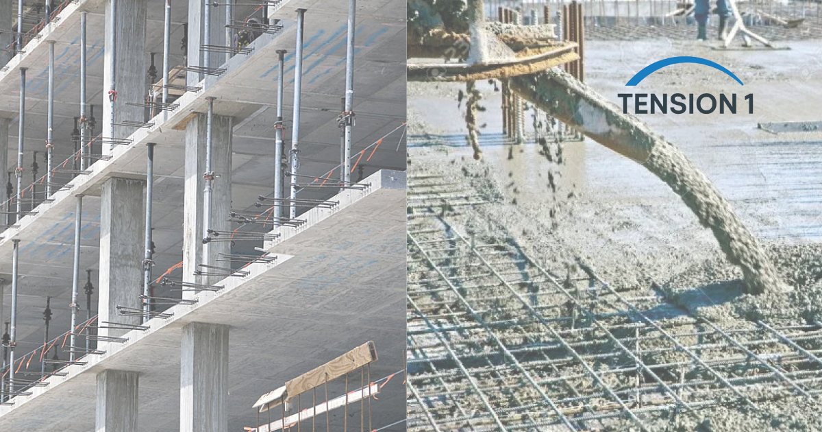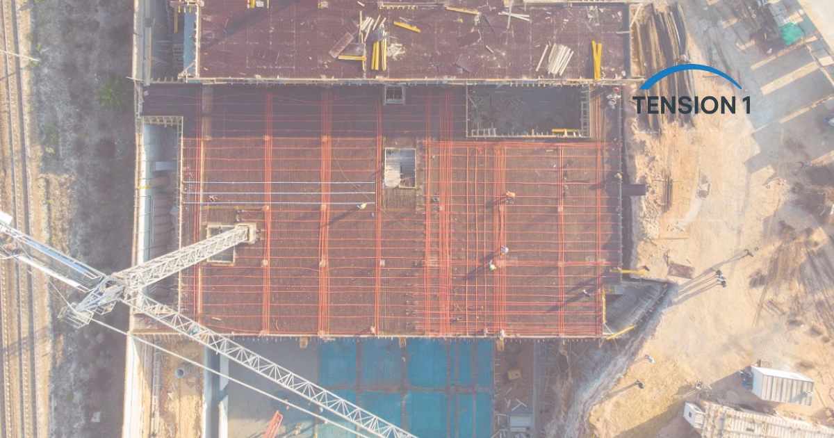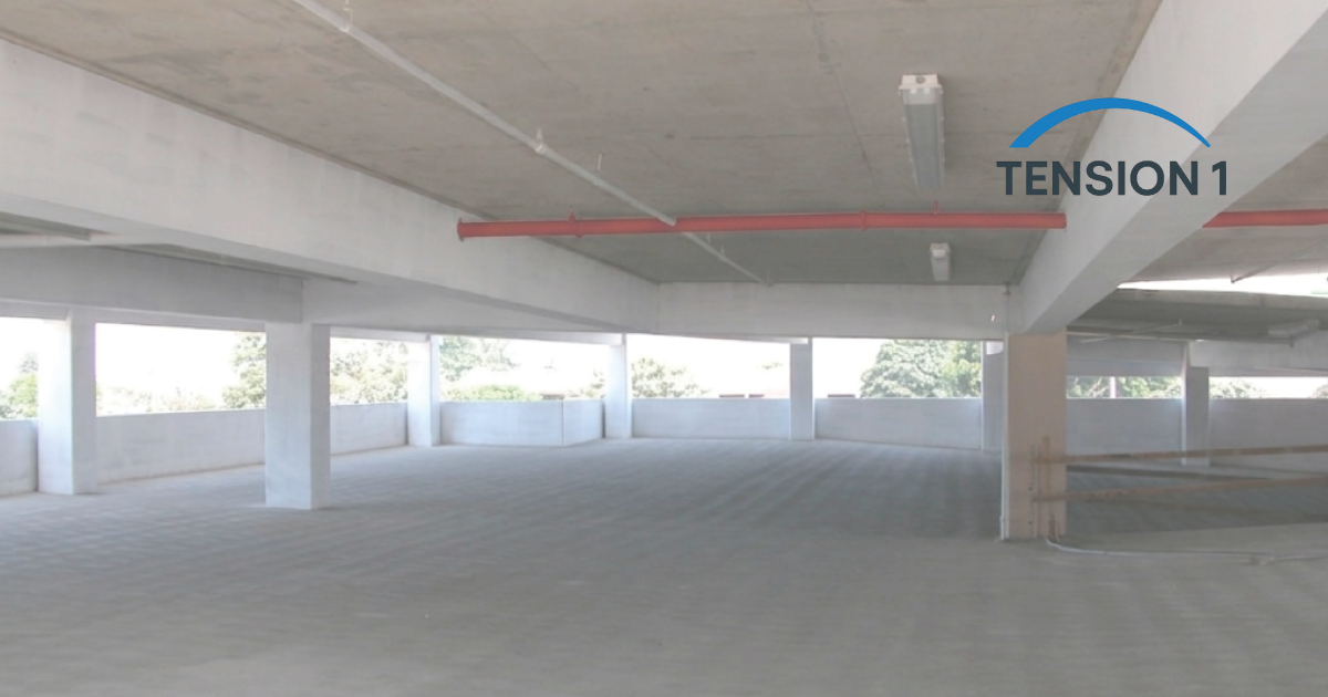
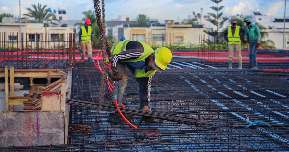
A post tension slab and a reinforced concrete slab can carry the same bay, but they do not give you the same building. The difference shows up in slab depth, floor-to-floor height, column and foundation loads, and the number of days the shoring stays in place. Yet the choice is usually made at schematic design, by habit, before anyone has run the numbers.
Once the forms are up, that decision is expensive to reverse. We have watched downstand beams eat parking clearance and push the MEP routing around the structure. We have also pushed PT onto a small, irregular slab where it never paid for itself. Both come from the same mistake: no real comparison.
This guide gives you the six criteria we use, the arithmetic and published benchmarks behind each one, and a parking structure where we ran both options in parallel.
In this guide:
- Why the decision is made too early
- How a post tension slab carries load differently
- 6 criteria to compare PT and reinforced concrete
- The Texas residential case: PT foundation or rebar slab on ground
- Case study: RC slab with beams vs unbonded PT flat plate
- When reinforced concrete is the better call
- What worked on site and what to watch
- The codes and documents that govern the comparison
Why the Post Tension Slab vs Reinforced Concrete Decision Is Made Too Early
A slab is the one structural element you cannot swap later: its depth sets floor-to-floor height and its weight sets column and foundation sizes. Reinforced concrete (RC) is the right answer on plenty of projects. The problem is that the alternative is never priced, and by the time a post-tensioned option comes up, the heights are set and the MEP is routed around the beams.
We have paid for that sequence ourselves. On one project the PT subcontractor came in after the RC scheme had been detailed, and we spent two weeks re-coordinating slab edges, pocket locations and anchorage zones. Nothing in that work was difficult. All of it was avoidable.
How a Post Tension Slab Carries Load Differently
Active precompression versus passive rebar
A conventionally reinforced slab is passive: the rebar does little until the concrete cracks, then it picks up the tension. A post tension slab is active. Grade 270 low-relaxation seven-wire strand, typically 0.5 in or 0.6 in per ASTM A416/A416M-26, is stressed once the concrete reaches its specified strength at stressing, then locked off at the anchors. This article compares RC with unbonded tendons, meaning greased strands in a plastic sheath that never bond to the concrete.
ACI 318-19 requires an average effective precompression of at least 125 psi in two-way PT slabs. On a 10 in slab, each foot of width holds 120 in2 of concrete, so that minimum is 15,000 lb, or 15 kip per foot. With an illustrative effective force of 26 kip per tendon, that is about one tendon every 21 in in the distributed direction, before load balancing asks for more.
Load balancing: one line of arithmetic
A draped tendon pushes up. For a parabolic profile, the balanced load is w = 8 P a / L squared, where P is the effective force, a is the drape and L is the span. On a 30 ft span with 26 kip and 6 in of drape, that gives about 0.116 kip/ft along the tendon line. Cut the drape to 4 in because the slab got thinner and the cover did not move, and it falls to about 0.077 kip/ft. One third of the balancing is gone.
That is why depth on a PT floor is a serviceability question before it is a strength question. Depth buys drape, drape buys balancing, and balancing keeps deflection and cracking inside the service limits that usually govern. Common practice balances 65 to 80 percent of the slab self-weight, according to the PCA article on two-way PT flat plate construction (2005).
6 Criteria to Compare a Post Tension Slab and a Reinforced Concrete Slab
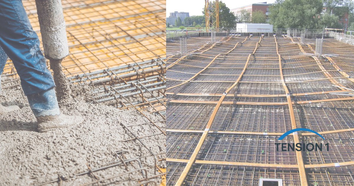
We run these six questions in order. If two or more point toward RC, price RC seriously. If none do, the burden of proof is on whoever wants to skip PT.
1. Span and slab depth
Take a 30 ft by 30 ft bay with 24 in square columns: the clear span is 336 in. For a nonprestressed flat plate with Grade 60 bars, the ACI 318-19 minimum thickness table gives ln/33 for an interior panel, 10.2 in, and ln/30 for an exterior panel without edge beams, 11.2 in. That is a floor before any deflection calculation, not an answer.
For a PT flat plate, the PCA article gives a preliminary span-to-thickness ratio of 45 for floors and 48 for roofs, which puts the same 30 ft span at 8 in. It reports a typical thickness reduction of 25 to 35 percent against mild reinforced slabs. One to three inches per floor adds up to building height and foundation load, as we show in PT vs RC slab efficiency in high-rise construction.
2. Floor plate size and repetition
PT carries fixed costs RC does not: a specialty subcontractor, a stressing crew, anchorage hardware with its own lead time, and tendon shop drawings. On large, repeated floors they disappear into the savings. As an engineering judgment, below roughly 5,000 ft2 on a single level they deserve their own line in the comparison. That is a rule of thumb from project work, not a published threshold: fixed cost divided by fewer square feet.
3. Geometry and openings
PT works best on a regular grid, banded over the column lines in one direction and distributed in the other. Re-entrant corners, offset columns and large openings force tendon sweeps and profile changes. An opening in the distributed direction is usually manageable. The same opening in the band changes the load path to the column, and the punching shear check has to be redone, not assumed.
4. Future penetrations and tenant changes
A reinforced slab forgives a core drill in the wrong place. A post tension slab does not. Cutting a stressed tendon releases its force suddenly and can injure people, so every later penetration starts with a qualified scanning contractor locating the tendons. PTI DC80.2 (2010), the Post-Tensioning Institute guide for creating openings and penetrations in existing unbonded PT slabs, sets out the procedure.
5. Local PT crew, inspection and schedule
Shoring stays until the tendons are stressed, so a stressing crew that arrives two days late blocks the cycle below. Confirm early who will install, stress and inspect. The PTI Level 2 Unbonded PT Installer and Inspector certification requires 500 hours of field experience and is valid for four years. Ask for the cards, not the claim.
6. Cost drivers, not cost per square foot
A single cost-per-square-foot figure hides the decision. Compare the drivers on the same bay:
- Concrete and formwork: thinner slabs and a flat soffit with no beam stems usually favor PT.
- Steel: PT trades mild steel tonnage for strand, anchors and stressing labor.
- Knock-on savings: lighter, shallower floors reduce columns, foundations, building height and facade.
We break these down with worked take-offs in post tension slab ROI: materials, formwork and timeline and PT vs rebar cost and performance for commercial builders. Less concrete also means less cement, the core of the carbon footprint advantage of post-tensioned slabs.
| Criterion | Post-tensioned slab | Reinforced concrete slab | What decides it |
|---|---|---|---|
| Behavior at service | Precompressed, designed uncracked | Cracked section, passive rebar | Crack sensitivity and exposure |
| Preliminary depth, 30 ft bay | About 8 to 9 in | At least 10.2 to 11.2 in | Deflection, punching shear, fire rating |
| Long spans | Flat plate usually feasible | Beams or drop panels often needed | Headroom and MEP routing |
| Fixed costs | Specialty sub, stressing, hardware | Standard trades | Slab area and number of levels |
| Irregular geometry | Best on regular grids | Tolerant | Offsets, corners, openings |
| Later penetrations | Tendons must be located first | Routine coring with scanning | Expected changes of use |
If a scheme is already drawn, a short technical consultation on PT vs RC system selection tells you whether a full comparison is worth running.
[tool:should-i-use-pt]
Post Tension Slab Foundation or Rebar Slab on Ground: The Texas Residential Case
In Texas, most people comparing PT and rebar are building or buying houses, and a slab on ground does not span between columns. It rides on soil that moves. Much of the Dallas-Fort Worth area sits on expansive clay, which swells when wet and shrinks when dry. A University of Texas at Arlington study (2010) classed soils sampled in Fort Worth and Dallas as highly plastic, expansive clays.
PTI DC10.5 is the standard for shallow PT foundations on expansive and stable soils. A PTI position statement notes it has set the design basis for essentially all unbonded PT slabs on ground in the U.S. since 1980. The 2019 edition is the one referenced by the International Building Code. A rebar slab can do the same job with deeper, more closely spaced stiffening beams, so the comparison turns on beam depth, excavation, steel and crew availability.
For owners, the difference comes later: a PT foundation cannot be cut or cored blind. We compare both in post-tension vs rebar in residential construction.
Case Study: RC Slab With Beams vs Unbonded PT Flat Plate on a Parking Structure
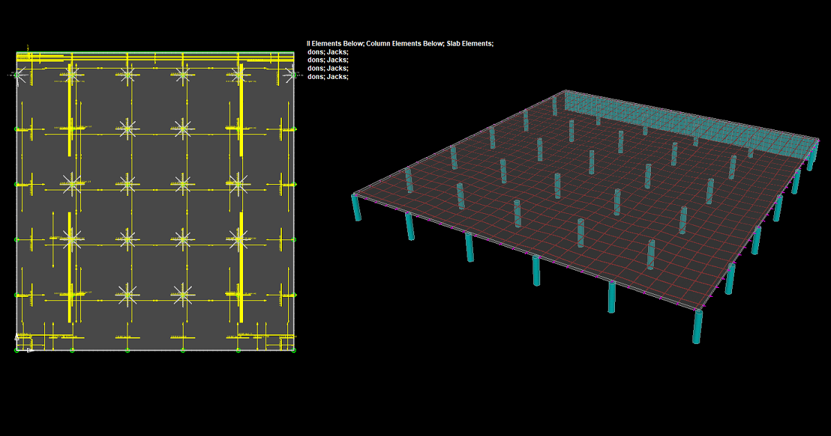
During design of a multi-level parking structure, the initial scheme was an RC slab on downstand beams. The beam depths were already clashing with the mechanical drawings on headroom. We ran an unbonded PT flat plate in parallel on the same grid.
| Parameter | RC option | PT option |
|---|---|---|
| System | RC slab on downstand beams | Unbonded PT flat plate |
| Slab thickness | 14 in | 10 in |
| Concrete, preliminary take-off | 773.26 yd3 | 544.11 yd3 |
| Difference | Reference | 229.15 yd3 less, about 29.6 percent |
| Self-weight at 150 lb/ft3 | 175 lb/ft2 | 125 lb/ft2 |
| Soffit | Beam drops | Flat |
The 229 yd3 is the headline, but the self-weight line matters more to the rest of the building. The PT floor is 50 lb/ft2 lighter on every level, and that reduction goes straight into the columns and foundations. The 28.6 percent thickness cut sits inside the 25 to 35 percent range the PCA article reports.
The flat soffit also solved the headroom conflict outright: no beam drops, no rerouted ducts. That benefit never appears in a take-off, and it was the one the project team valued most. The parking-specific analysis is in post tension slab ROI for parking garages: spans and depth.
How we ran the comparison
Both options used the same grid, load combinations, concrete strength and exposure. For the PT option we set a load balancing target as a share of the slab self-weight, checked service stresses against the uncracked limit for two-way PT slabs, compared calculated deflections with the ACI 318-19 permissible deflection limits, and checked punching shear on the critical section at d/2 from the column face, including unbalanced moment at edge columns. Quantities come from a preliminary take-off.
When a Reinforced Concrete Slab Is the Better Call
We got this one wrong once. We pushed PT onto a 4,000 ft2 slab with irregular column spacing because the system had won so clearly elsewhere. The savings came out marginal, the tendons needed several profile changes, and the shop drawings took longer than RC detailing would have. RC was the pragmatic call.
These are the conditions where we now start from RC and ask PT to prove itself:
- Small slab areas: on a single level below roughly 5,000 ft2, mobilization and hardware lead time can absorb the savings.
- Irregular grids: offsets and closely spaced columns complicate banding more than they complicate rebar.
- Frequent future penetrations: uses that will core and trench for decades are simpler and safer in RC.
- Short spans and modest loads: below about 20 ft column spacing, a conventional two-way slab is usually thin enough.
- No qualified PT crew: if nobody local can install, stress and inspect on schedule, the risk moves against PT.
When neither system fits cleanly, see our builder's guide to post tension slab alternatives.
What Worked on Site and What to Watch
What worked on site
- Tendon drawings before MEP rough-in: issuing the tendon layout before sleeves were placed resolved nearly every sleeve and tendon conflict on paper. No other step saved as much schedule.
- Banded and distributed layouts on rectangular bays: a simple pattern for the ironworkers, and two-way behavior consistent with the analysis model.
- Elongation logs checked against calculated values: this caught two anchor seating anomalies before the stressing pockets were closed, and both were corrected at negligible cost. ACI 318-19 Section 26.10.2 requires any difference above 7 percent between gauge force and elongation-based force to be explained and corrected. STRUCTURE magazine's best practices for PT elongation records explains how to read them.
What to watch
- Late PT subcontractor engagement: it cost us two weeks of re-coordination. Engage the PT sub at design development.
- The stressing access strip: on a tight urban footprint, adjacent trades occupied the clear zone the jacks needed. Protect it on the site logistics plan.
The Codes and Documents That Govern a Post Tension Slab Comparison
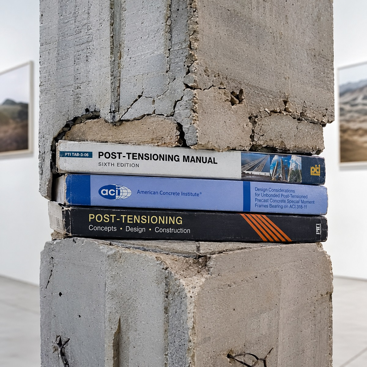
This article references ACI 318-19. ACI released ACI CODE-318-25 in 2025, and the edition that governs your project is the one adopted by your authority having jurisdiction. Check which one applies before using any reference here.
- ACI 318-19: Chapters 8, 22, 24 and 26 for two-way slabs, punching shear, service behavior and construction.
- PTI DC20.9-11: Guide for Design of Post-Tensioned Buildings, with preliminary design tables.
- PTI DC10.5-19: shallow PT foundations on expansive and stable soils.
- ASCE/SEI 7-22: design loads and load combinations.
PTI documents are available from the Post-Tensioning Institute. The governing code edition and the project documents take precedence over this article, and sealing and approval belong to the licensed engineer of record. How we source, date and correct technical content is set out in our editorial policy, and the background behind these projects is on our about page. For the fundamentals, start with the complete post tension slab guide.
Get a Quantified PT vs RC Comparison Before You Lock the Structure
The cheapest moment to compare two slab systems is before the heights are set. If you are weighing a post tension slab against RC, we run the comparison on your grid and loads, from load balancing to punching shear and a side-by-side take-off, with every assumption stated so your team can check it line by line.
Our work is independent technical support: we produce calculations, tendon layouts and documentation, and the licensed engineer of record reviews, seals and remains responsible for the design. See our post-tension slab design, optimization and diagnostics services, or send us your structural grid and loading to scope a comparison.