In long-span concrete construction, the most persistent problems we encounter are not related to material strength — they are related to deformation. A post tension slab is the most reliable structural response to two failure modes that plague conventionally reinforced concrete: excessive midspan deflection and uncontrolled cracking under service loads.
When a slab spans 30 ft or more between supports, gravity loads generate bending moments that standard rebar simply cannot address efficiently. The result is a slab that deflects visibly, develops tension cracks that compromise serviceability, and may trigger partition damage, waterproofing failures, and costly warranty claims months after handover.
The financial consequences are rarely abstract. On a mid-rise commercial project in the Dallas-Fort Worth area we consulted on, a 40 ft transfer slab designed with conventional reinforcement was showing measured deflections of L/280 at 18 months after construction — well below the ACI 318-19 serviceability limit of L/480 for elements supporting non-structural components. That triggered $190,000 in remediation costs before the tenant fit-out was complete.
Post-tensioning solves this by introducing a controlled compressive force into the concrete before service loads are applied. This pre-compression counteracts the tensile stresses that cause cracking and significantly reduces net deflections. In this article, we explain exactly how that works mechanically, how tendon profiles are selected for long-span conditions, and where on-site execution can make or break the intended structural performance.
For a broader overview of post-tensioned concrete systems, see our complete guide: The Ultimate Guide to Post-Tension Slabs: Advantages, Design, and Longevity.
The Mechanics of Pre-Compression: Why Concrete Needs Help in Tension
Concrete is a material that performs exceptionally well in compression and poorly in tension. Its tensile strength is typically between 8 and 12 percent of its compressive strength. For a 4,000 psi structural concrete mix, that means the material begins to crack at tensile stresses as low as 320 to 480 psi. In a long-span slab under a 100 psf service load, midspan tensile stresses can reach 600 to 900 psi without prestress — well past the cracking threshold.
Post-tensioning reverses this by applying a longitudinal compressive force through high-strength steel tendons stressed to working loads typically between 26 kip and 33 kip per tendon, depending on the strand area and system used. When the concrete is pre-compressed to a net stress of 125 to 250 psi across the gross slab section — a common design target per PTI DC80.3 — the effective tensile stress under service loading drops below the modulus of rupture. The slab behaves as an uncracked section across its service load range.
This is not a theoretical benefit. It translates directly into structural and financial performance. An uncracked section has a moment of inertia two to three times greater than a cracked reinforced concrete section of the same depth. That stiffness difference is what allows a post-tensioned slab to span 35 to 50 ft at thicknesses that would be structurally unviable with conventional reinforcement.
Effective Prestress: The Number That Drives Serviceability
The parameter we track most closely on PT slab design is the effective prestress, noted as fpe. This is the prestress remaining in the tendon after all losses including elastic shortening, creep, shrinkage, and friction. For unbonded monostrand systems common in Texas residential and commercial slab-on-grade construction, we typically design for fpe between 145 ksi and 175 ksi, depending on the tendon length and stressing configuration.
The balance load concept, derived from PTI DC80.3 and ACI 318 Section 8.10, is our primary design lever. By matching the upward equivalent load produced by the draped tendon profile to approximately 60 to 80 percent of the sustained dead load, we can effectively neutralize long-term deflection from permanent loads. Short-term live load deflections remain, but they occur on a stiff, uncracked section and recover elastically when the load is removed.
Tendon Profile Selection for Long-Span Slabs: Drape is Everything
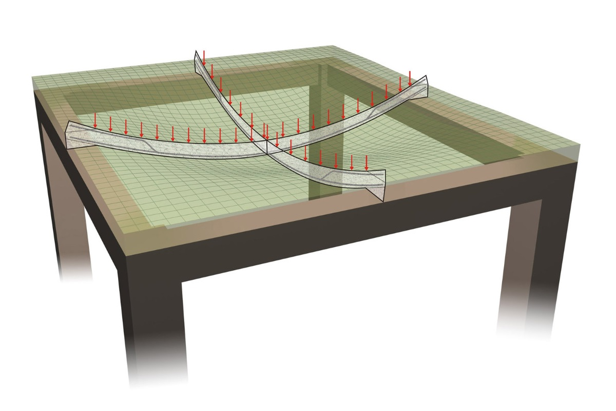
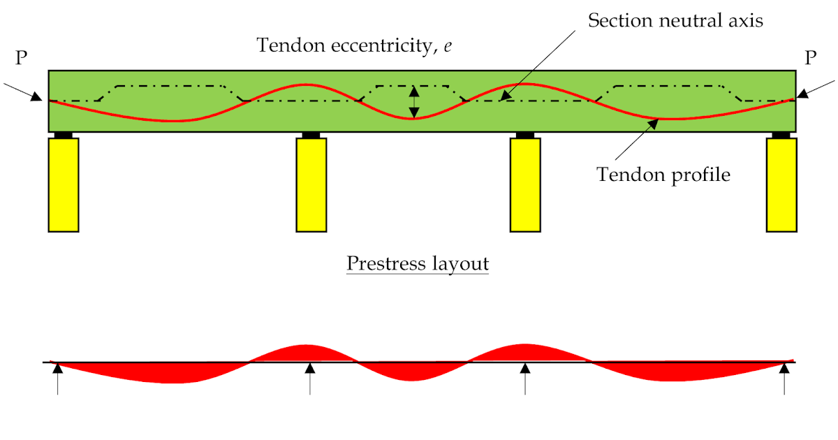
The structural benefit of post-tensioning in a long-span slab is almost entirely a function of tendon profile geometry. A flat tendon produces almost no transverse load on the concrete. A properly draped tendon — anchored at the slab centroid at end supports and reaching its lowest point at midspan — generates a distributed upward force that directly offsets gravity loads.
For a simple-span condition, the maximum theoretical drape is limited by slab depth minus cover requirements at the top (typically 1 in. clear to duct per ACI 318-19 Section 26.6.2) and bottom (1 in. clear for slabs in dry conditions). On a 10 in. thick slab with standard cover, effective drape is approximately 6.5 to 7 in. at midspan. For a 40 ft span stressed to 26 kip per tendon, that geometry produces a balance load of approximately 6 psf per tendon — a figure we verify during the design phase against the tributary dead load.
In continuous slabs, the profile reverses over interior supports. The tendon rises to a high point at each intermediate support to counteract hogging moments, then drops back to the midspan sag for the next span. Getting this reverse-curvature profile detailed and constructed correctly is one of the most common sources of field deviation we see on Texas projects.
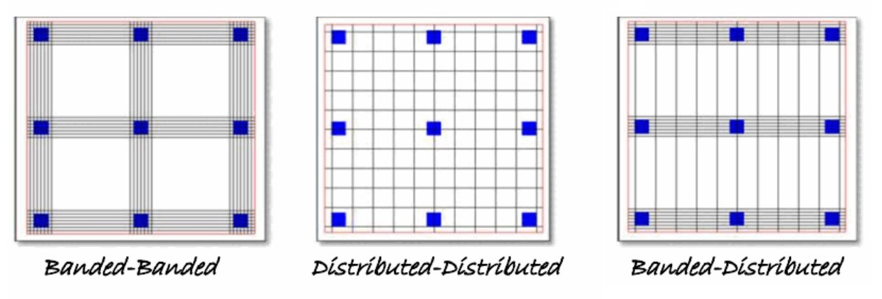
Banded vs. Distributed Tendon Layouts in Long-Span Conditions
For long-span slabs in one direction, particularly those supported on isolated columns without beams, we use a banded layout in the primary span direction and a distributed layout perpendicular to it. This is consistent with the PTI DC80.3 recommendations for two-way PT flat plates. The banded direction collects load through column strips; the distributed direction provides minimum average prestress across the full panel width.
For detailed PT tendon layout and detailing principles, see: The Ultimate Guide to Post-Tension Slabs — Design Parameters.
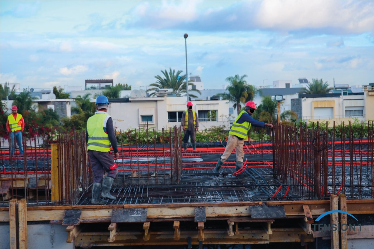
On-Site Execution: Where PT Performance Is Won or Lost
We have reviewed PT slab designs that were structurally sound on paper but performed below expectation in the field. In almost every case, the deviation was not in the calculations — it was in the construction sequence, the stressing operations, or the as-built tendon geometry. The following field observations are drawn directly from site reviews and post-construction inspections we have conducted on PT slab projects in Texas.
We evaluated these conditions by reviewing as-built stressing records against engineer-calculated elongation tables, cross-checking measured tendon cover with shop drawings, and conducting visual inspections of pour sequences and joint locations.
| What Worked On-Site | What Did Not Work |
|---|---|
| Banded tendon layout in one direction concentrated force where punching shear was highest, reducing required rebar congestion. | Flat tendon profiles in low-span zones added unnecessary friction losses and reduced effective prestress at midspan. |
| Targeting an average effective prestress of 125 psi across the full slab panel controlled long-term creep deflections measurably. | Stressing from one end only on runs exceeding 120 ft produced elongation shortfalls of 8 to 12%, indicating excessive friction and wobble. |
| Coordinating pocket locations with the architectural reflected ceiling plan eliminated field conflicts and prevented accidental tendon cuts. | Skipping the intermediate temperature reinforcement bars in the short direction led to visible shrinkage cracks at construction joints within 30 days of pour. |
| Performing elongation checks against engineer-calculated theoretical values at every jack operation caught two draped tendons that were obstructed by embedded conduit. | Rushing the stressing sequence before concrete reached the specified 75% of design strength caused localized crushing at the anchorage zone. |
Stressing Sequence and Timing
ACI 318-19 Section 26.10.2 requires that stressing not begin until the concrete has achieved the minimum compressive strength specified in the contract documents, with a common threshold of 3,000 psi or 75 percent of f'c, whichever governs. On Texas pours during summer months, that threshold can be reached in 48 to 72 hours. We always require a minimum of two cylinder breaks before authorizing stressing operations, regardless of schedule pressure.
Partial stressing — where a subset of tendons are stressed to a reduced load at an early concrete age — is permitted under PTI DC80.3 guidelines but must be documented and reviewed for the specific project conditions. We have used partial stressing successfully on large-footprint slabs to allow earlier form stripping without overloading the fresh concrete.
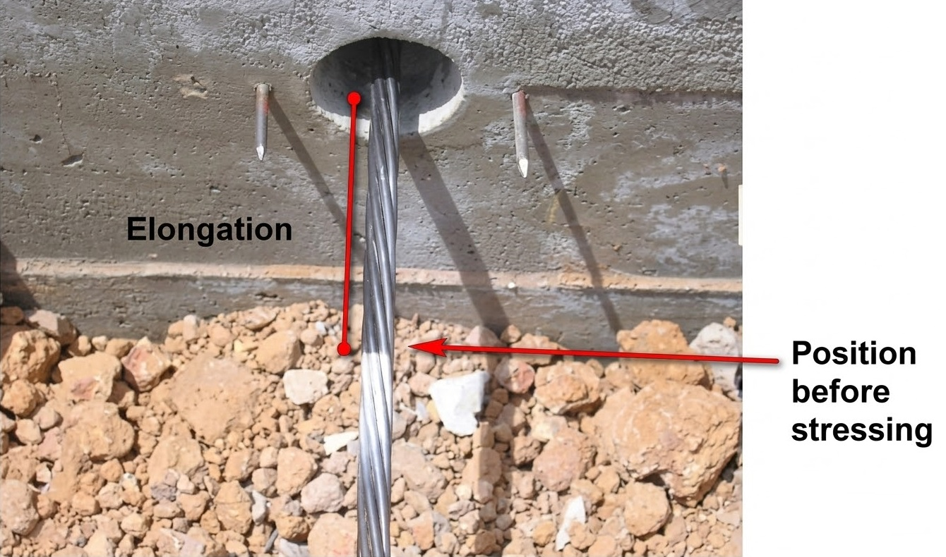
Elongation Checks: The Field Verification No PT Slab Should Skip
Theoretical tendon elongation is calculated by the design engineer based on the tendon layout, friction coefficients (mu and wobble factor K), and the applied jacking load. ASTM A416 and PTI specifications require that measured elongations agree with theoretical values within plus or minus 7 percent.
On a Dallas office slab we reviewed, three tendons in a banded strip showed elongations 14 percent below theoretical. Investigation revealed that a bundle of 1.5 in. conduit runs had been routed directly beneath two tendons, physically blocking the intended drape geometry. The tendons were not achieving the designed sag, which reduced both the balance load and the effective eccentricity. The fix required the contractor to install supplemental mild reinforcement in the affected strip and revise the deflection calculations for that panel.
Crack Control in Post-Tensioned Long-Span Slabs: Code Limits and Practical Checks
ACI 318-19 Section 24.5 governs the permissible concrete tensile stresses for two-way PT slabs under service loads. For slabs not exposed to corrosive environments, the net average compressive stress after all prestress losses must not fall below 125 psi. The tensile stress at any point must not exceed 6√f'c at transfer and 7.5√f'c under full service loads — for 4,000 psi concrete, that equates to approximately 380 psi and 474 psi respectively.
Meeting these limits analytically is necessary but not sufficient. We also check the column strip moments and ensure that the banded tendon force is sufficient to maintain net compression at the top fiber over each support under pattern loading. Pattern loading — where live load is applied on alternate spans to maximize hogging moments — is frequently underweighted in preliminary designs but can govern the top fiber tension check at interior columns.
Temperature and Shrinkage Reinforcement: The Overlooked Crack Initiator
PT slabs in Texas are subject to significant temperature swings during construction before stressing operations begin. ACI 318-19 Section 24.4.3 requires minimum temperature and shrinkage reinforcement in each direction at rates that can be reduced in PT slabs due to the prestress contribution — but they cannot be eliminated entirely. We have seen projects where the short-span reinforcement was omitted based on a misreading of the code, resulting in parallel shrinkage cracks at 6 to 10 ft spacing visible within 30 days of pour.
For long-span slabs with tendons in both directions, we specify minimum mild steel at 0.0018 times the gross cross-sectional area in each direction unless the applied average prestress exceeds 100 psi in that direction across the entire slab width. This provides a minimum crack width control mechanism even during the early-age shrinkage phase before stressing.
For a full breakdown of how PT slabs perform across their service life compared to conventional RC, see our complete guide to PT slab advantages, design, and longevity.
Deflection Control: Calculating Long-Term Performance Under Sustained Loads
The deflection check for a PT slab is more involved than for a conventionally reinforced section because the effective prestress, the creep multiplier, and the balance load must all be integrated into the calculation. ACI 318-19 Table 24.2.2 limits total deflections to L/240 for members not supporting or attached to non-structural elements, and to L/480 for members that are, where L is the clear span.
For a 40 ft clear span slab supporting glass partitions, that L/480 limit equals 1 inch of permissible post-construction deflection. To stay within that envelope, the balance load from the PT system must be calibrated carefully. Underbalancing the dead load produces excessive long-term creep deflection. Overbalancing it risks upward camber under dead load only, which can cause unintended ponding of rainwater on roof slabs or separation of floor finishes from the structural slab.
We calculate the net immediate deflection from unbalanced load (total service load minus balance load) using the gross section moment of inertia for uncracked PT sections. Long-term deflection is then estimated by applying the ACI 318 creep multiplier, which ranges from 1.4 to 2.0 depending on the sustained load duration and the compression reinforcement ratio, if any. For slabs with no compression reinforcement and loads sustained beyond 5 years, the multiplier is 2.0.
A Sample Deflection Check for a 40 ft Long-Span PT Slab
Given: Simple-span PT flat slab, 40 ft clear span, 10 in. thick, f'c = 4,000 psi, applied service load = 150 psf (dead + live), balance load = 95 psf.
Unbalanced load: 150 − 95 = 55 psf
Immediate midspan deflection (uncracked, gross section, δ = 5wL⁴ / 384EI): ≈ 0.38 in. (verify with project-specific section properties)
Long-term estimate (creep multiplier = 2.0): 0.38 × 2.0 = 0.76 in. total long-term deflection under sustained unbalanced load.
ACI 318 limit (L/480): (40 × 12) / 480 = 1.00 in. — calculated 0.76 in. falls within the permissible range with acceptable margin. ✓
This type of worked example is what we include in our detailed calculation packages for engineering consulting clients. It gives contractors and drafters a traceable record from design assumption to code compliance check.
Frequently Asked Questions
What is the minimum average effective prestress required in a post tension slab per ACI 318?
ACI 318-19 Section 8.6.2.1 requires a minimum average effective prestress of 125 psi in each direction for two-way PT slabs not exposed to corrosive environments. In regions with aggressive soil or moisture conditions, higher values are typically required and should be confirmed with the engineer of record for the specific project.
Can a post-tensioned slab eliminate cracking entirely?
Not entirely, and the goal is not to eliminate all cracking but to maintain crack widths below serviceability thresholds. PT slabs in service can develop hairline cracks at construction joints, around penetrations, or where temperature reinforcement is insufficient. Proper pre-compression reduces crack widths significantly compared to conventionally reinforced slabs, but field execution of the stressing sequence and the provision of temperature reinforcement remain essential.
How does tendon profile affect deflection in long-span PT slabs?
Tendon profile geometry determines the balance load — the upward equivalent uniform force generated by the curved tendon under tension. A deeper sag at midspan produces a greater balance load for the same tendon force. Maximizing the drape within the cover constraints of the slab section is therefore the most efficient way to increase deflection control without increasing tendon quantity or jacking load.
What are the most common causes of PT slab deflection problems in the field?
The most common causes are insufficient tendon drape due to obstructions from embedded MEP conduit, stressing below the required concrete strength which reduces effective prestress, missing or underspecified temperature reinforcement in the short direction, and balance loads that are set too low relative to the sustained dead load, leading to long-term creep deflections that exceed ACI limits.
Where can I find reliable code references for PT slab design in Texas?
The primary references are ACI 318-19 Chapters 8 and 24 for two-way slab design and serviceability, PTI DC80.3 for unbonded single-strand tendon systems, and ASCE 7 for load combinations. Texas construction projects must also comply with the applicable edition of the International Building Code (IBC) as adopted by the jurisdiction. The Post-Tensioning Institute (PTI) publishes these documents at post-tensioning.org.
Technical Consulting for PT Slab Projects
If you are working on a long-span post-tensioned slab and need an independent engineering review, a deflection and crack control verification, or a field stressing protocol, our Technical Consulting service is built for exactly that type of engagement. We provide tendon profile reviews, elongation check validation, ACI 318 and PTI DC80.3 compliance documentation, and written engineering narratives for contractor or permit submittal.
Contact TensionOne →External references: ACI 318-19 — American Concrete Institute. PTI DC80.3-20 — Post-Tensioning Institute. ASCE 7-22 — American Society of Civil Engineers. ASTM A416 — Standard Specification for Low-Relaxation Seven-Wire Strand.