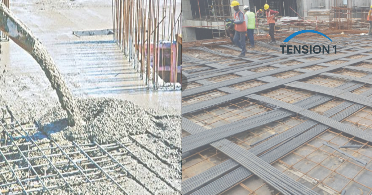
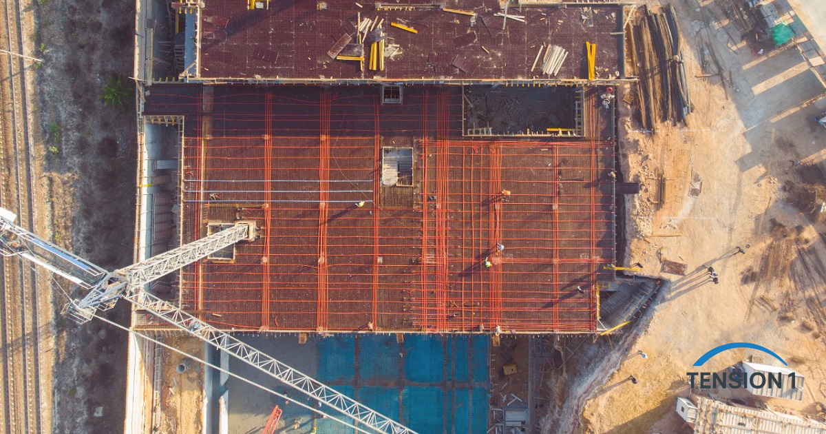
Conventional reinforced concrete slabs crack. That is not a design flaw we can engineer away entirely: it is an inherent consequence of concrete's tensile weakness and shrinkage. What we can control is how much cracking occurs, where it occurs, and how it affects long-term performance. The post tension slab addresses that problem at a fundamental level by introducing a continuous compressive force into the concrete before service loads are ever applied.
In more than six years of experience designing and reviewing PT systems across Africa, Europe, and more recently the Texas construction market, we have seen what happens when a PT slab is properly designed, and when it is not. A well-executed post-tensioned concrete system routinely outperforms conventional reinforced concrete in span capability, slab thickness efficiency, crack control, and service life. A poorly designed one, whether due to incorrect tendon profiling, underestimated friction losses, or insufficient cover, creates problems that are expensive and disruptive to remedy.
This guide covers how PT slabs work, the advantages they offer over conventional RC, the design parameters that govern them, and what drives longevity in the field. It is written for general contractors evaluating system selection, drafters laying out tendon plans, technicians checking stressing records, and owners who want to understand the slab under their building.
In this guide
- What is a post tension slab and how does it work?
- The structural advantages of PT slabs over conventional RC
- Post tension slab design: key parameters and code requirements
- Long-term performance and longevity
- PT slab vs. conventional RC slab: side-by-side comparison
- Go deeper: the TensionOne post tension slab library
1. What Is a Post Tension Slab and How Does It Work?
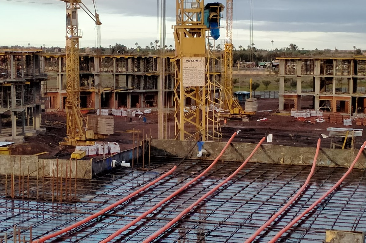
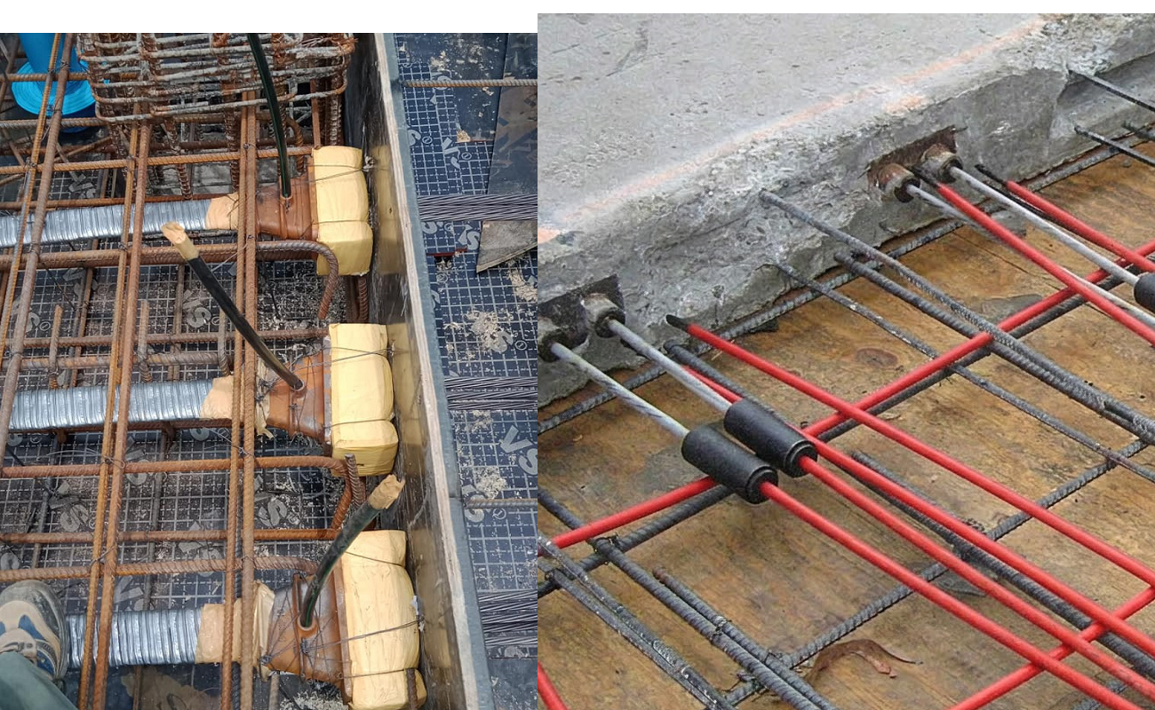
A post tension slab is a concrete slab in which high-strength steel tendons are tensioned after the concrete has reached a specified minimum strength. In the residential and light commercial sector, these are typically 270 ksi low-relaxation strand to ASTM A416. In the unbonded system most common in the U.S. market, each tendon is a 0.5 in. or 0.6 in. strand coated in corrosion-inhibiting grease and enclosed in a plastic sheath. The sheath prevents the strand from bonding to the concrete, so it can move freely during stressing.
The Mechanism of Precompression
When a hydraulic jack grips the tendon tail and pulls against the hardened concrete through the anchor, two things happen at once. The strand is stretched to its jacking stress: ACI 318 caps it at 80 percent of the strand's strength, about 216 ksi for 270 ksi strand. And the reaction at the anchor compresses the concrete along the tendon's path. After friction, anchor set, elastic shortening, creep, shrinkage and relaxation, the effective stress left in the strand is lower, typically 145 to 175 ksi in our designs. That sustained compression in the concrete is the defining characteristic of post-tensioned concrete.
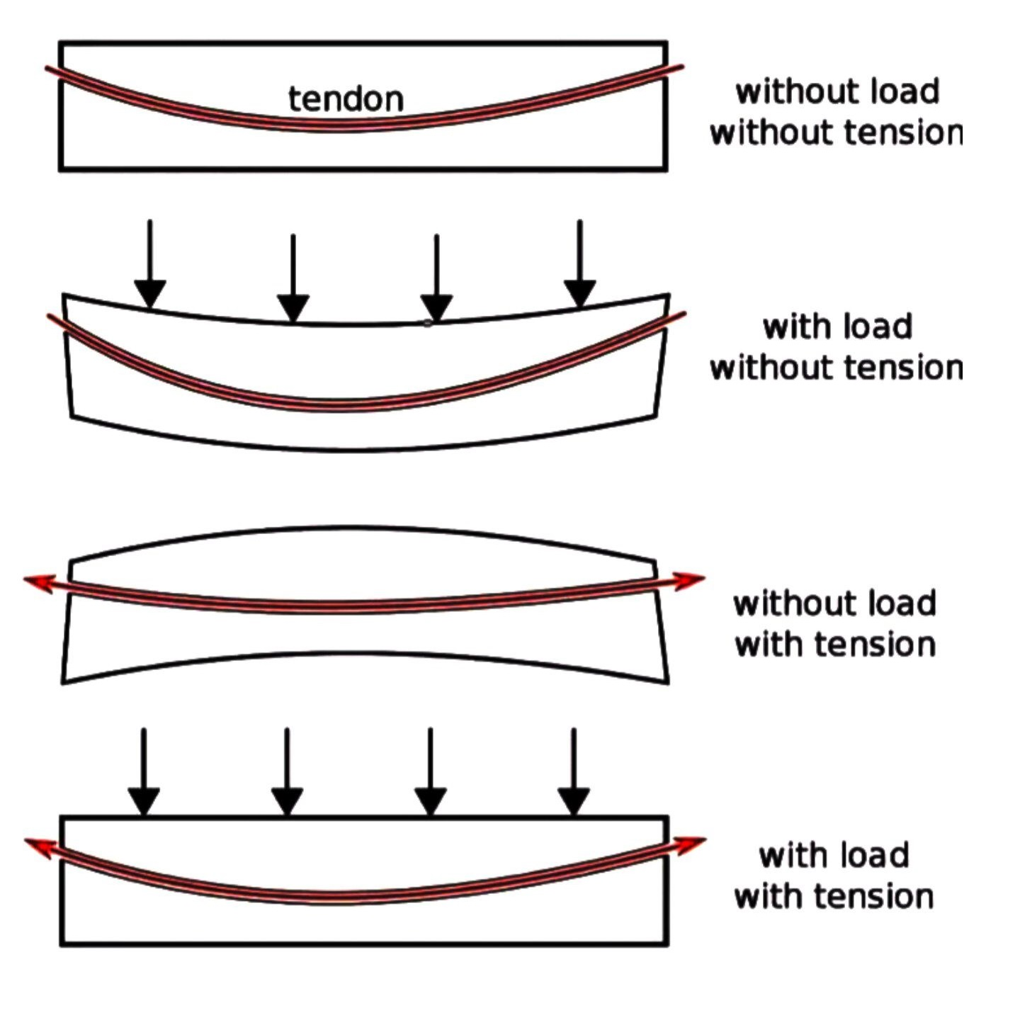
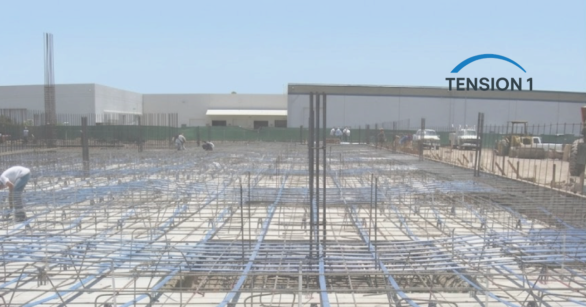
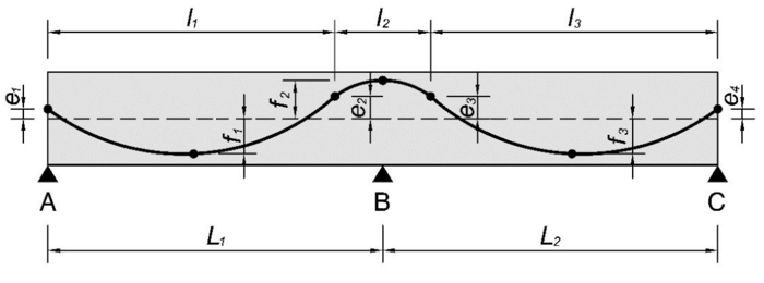
In an elevated flat plate, the tendon does not run straight through the section. It follows a profile that sits high over the columns and supports and sags low at mid-span. The curvature of that profile produces an upward equivalent load along the span that counteracts part of the gravity load. Under the load-balancing method introduced by T.Y. Lin in 1963, engineers typically balance 60 to 80 percent of the sustained dead load. That keeps the slab close to flat under everyday service conditions.
Unbonded vs. Bonded PT: What We See in Texas
In most residential and light commercial post-tension slabs across Texas, unbonded monostrand is the standard, including podium slabs and most parking structures. Bonded post-tensioning, where the duct is grouted after stressing to bond the strands to the concrete, is more common in bridges, transfer girders and special structures. For the foundations and podium slabs we see most often in the Dallas market, unbonded PT is cost-effective and well understood by local contractors. Its design is governed by ACI 318-19 and its hardware by PTI M10.2-17. How the two systems age, and what fails in each, is covered in bonded vs. unbonded post tension slab systems.
Field Note from Joseph
On a recent Dallas foundation pour, we specified a tendon profile that placed the high point 1 in. below the top slab surface at slab edges and the low point 1.5 in. above the bottom at mid-panel. Getting that profile elevation verified before the concrete truck arrives matters more than most contractors realize. A tendon that runs flat through the section instead of following the specified drape delivers a fraction of the intended load balancing, and the resulting mid-panel deflections can become visible within the first year of service.
2. The Structural Advantages of PT Slabs Over Conventional RC
The choice between post-tensioned and conventional reinforced concrete is an engineering and economic question, not only a materials question. We evaluate it against the actual project constraints: spans, loads, depth limits and long-term serviceability.
Span Efficiency
The most immediate advantage of a post tension slab is span efficiency. For a conventional two-way flat plate, ACI 318-19 sets a minimum thickness of ln/33 for interior panels with Grade 60 rebar when deflections are not calculated. For PT flat plates, PTI guidance uses span-to-depth ratios of about 45 for floors. In a real-world scenario we analyzed for a Dallas-area multi-tenant office fit-out, switching from conventional RC to unbonded PT allowed the structural depth to drop from 9 in. to 7 in. for a 28-ft bay, freeing 2 in. of floor-to-floor clearance that was critical for MEP routing.
The same principle carries further. It is what makes long spans and large overhangs possible, as covered in how post-tensioning prevents cracking and deflection in long-span concrete structures. Our case study on PT cantilevers in modern architectural design takes it to the extreme.
[tool:pt-slab-depth-calculator]
Crack Control Through Active Precompression
Conventional reinforced concrete controls cracks passively. The design accepts cracking, and the bar spacing rules of ACI 318-19 Section 24.3 keep crack widths acceptable. Post-tensioned concrete is active: the precompression has to be overcome before any net tension develops. ACI 318-19 Section 24.5 requires two-way PT slabs to be designed as Class U, which means uncracked, with service tension limited to 6√f'c, about 380 psi for 4,000 psi concrete.
In practice, properly designed and built PT slabs on stable subgrades show far fewer surface cracks than their RC counterparts. We have reviewed slab systems installed in Dallas in the early 1990s that show no structural cracking despite decades of Texas thermal cycling.
Construction and Material Efficiency
Post-tensioned slabs typically use 20 to 30 percent less concrete than an equivalent conventional slab, because the thinner section performs as well. Lighter slabs also reduce the load on walls, columns and foundations, so the savings compound. Less concrete also means less embodied carbon, which owners and public agencies increasingly ask about. The worked numbers are in post tension slab vs. reinforced concrete: the embodied carbon comparison. Where forming and shoring costs are significant, stressing can also allow earlier form stripping, depending on the concrete's strength gain.
What Worked on Site
- Thinner slabs on Dallas residential foundations consistently reduced shrinkage-driven cracking during the initial cure period compared to thicker conventional RC pours under the same conditions.
- The ability to eliminate most intermediate control joints in PT slabs simplified the finishing operation and improved floor flatness results (F-number performance).
- PT tendons provide a practical load path indicator during diagnostics: the tendon profile and stress state can be checked to verify that the slab is performing as designed.
What Did Not Work on Site
- Stressing was delayed on one project due to a dispute over acceptance of concrete cylinders. When the slab sat un-stressed for over 10 days in summer heat, thermal shrinkage cracking developed before pre-compression was applied. Stressing schedule adherence is not negotiable.
- On a renovation project, a mechanical contractor cut through three tendons without contacting the structural engineer. Unbonded PT tendon repair is expensive and disruptive. Post-installation awareness among trades is a persistent challenge.
- In one case, grease contamination on the anchor bearing surface caused three wedge sets to slip. Inspection of anchorage hardware before concrete is placed is a non-optional quality step.
If a tendon has already been cut on your project, our emergency protocol for a cut post-tension tendon covers the first hours.
3. Post Tension Slab Design: Key Parameters and Code Requirements
We work through serviceability and strength checks in sequence. Load combinations come from ASCE 7-22 and design provisions from ACI 318-19. ACI CODE-318-25 is now the current edition, and the one that applies depends on the code adopted by the local jurisdiction. Tendon hardware follows PTI M10.2-17. Slab-on-ground foundations follow PTI DC10.5-19, which the International Building Code names for slab-on-ground foundations on expansive soils.
Minimum Average Precompression
ACI 318-19 Section 8.6.2.1 requires a minimum average effective precompression of 125 psi for two-way PT slabs. This is a floor, not a target. Slab-on-ground foundations work to a different minimum. PTI DC10.5 requires at least 50 psi after losses, and STRUCTURE magazine reports typical values of 60 to 100 psi. In both cases, what matters for the checks is the effective prestress after losses, which is why the loss calculation has to be done carefully before the design is finalized.
Tendon Profile and Drape
The tendon profile governs the equivalent load the tendon applies to the concrete. For a parabolic profile, the balanced load is w = 8Pa/L², where P is the effective force, a the drape and L the span. The drape is the vertical distance between the high and low points of the tendon within a span. We calculate drape for each tendon direction, because plan irregularities, slab edges, column sizes and cover requirements all limit the profile that can physically be built.
Code Reference
ACI 318-19 Chapter 8 (two-way slabs), Section 24.5 (permissible stresses), Chapter 25 (anchorages) and Chapter 26 (construction documents and inspection) govern elevated two-way PT slabs. PTI M10.2-17 covers unbonded tendon hardware. PTI DC10.5-19 covers PT slab-on-ground foundations.
Friction and Elastic Shortening Losses
For unbonded PT, friction losses depend on the curvature friction coefficient (μ) and the wobble coefficient (K). Both should be taken from the tendon supplier's data for the specific sheathing and grease system. On a recent project with a 65-ft run of tendon, we calculated friction and anchor set losses of approximately 12% of the jacking force, which reduced the effective post-stressing force meaningfully and required adjustment to the number of tendons per band.
Punching Shear at Column-Slab Connections
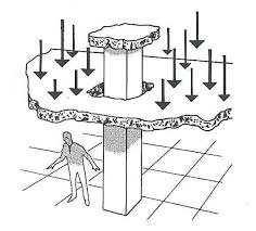
In PT flat plates, punching shear at the columns is one of the critical failure modes, checked under ACI 318-19 Chapter 22. The vertical component of the inclined tendon force at the column contributes to shear resistance. That is why the tendon profile near column lines matters for strength, not only serviceability. In banded-distributed layouts, the banded tendons over the column lines add both bending capacity and shear enhancement at the column. We verify punching shear under gravity and under unbalanced moment, which governs at edge and corner columns.
4. Long-Term Performance and Longevity: What the Field Tells Us
The longevity of a post tension slab is not mainly a materials question. Properly specified concrete and strand last a long time. Longevity is a corrosion protection and detailing question.
Corrosion as the Primary Long-Term Risk
The strand works at high sustained stress for its whole life. Stressed high-strength steel exposed to chlorides or moisture is vulnerable to pitting, stress corrosion cracking and hydrogen embrittlement. That is why the grease and sheath of an unbonded tendon are not a construction convenience. They are the primary corrosion barrier. ACI 318-19 Chapter 20 sets minimum concrete cover, and we treat it as a minimum, not a target, particularly where slabs face soil or exterior exposure.
We have reviewed PT slab systems in the Dallas area where anchor pockets were left unsealed for extended periods after stressing. In several cases, moisture infiltrated through the pocket directly to the strand-anchor interface. That is an avoidable corrosion path. Pockets should be closed promptly after stressing, with a fill compatible with the PT coating, and in aggressive exposure with an encapsulated system to PTI M10.2-17. The warning signs of corrosion and their repair costs are covered in the 5 warning signs your post-tension slab needs immediate expert repair and in our guide to tendon corrosion inspection and preservation.
Expansive Soils and Slab-Soil Interaction in Texas
The main service-life challenge for Texas PT foundations is not the PT system. It is the expansive clay under most of the Dallas area. The Virginia Department of Energy cites an ASCE estimate that one quarter of U.S. homes have suffered damage from expansive soils. As soil moisture changes with the seasons, the clay swells and shrinks unevenly under the slab. A well-designed PT foundation handles this with enough stiffness and precompression to bridge the differential support without cracking. But the design must be based on the real soil data, and the as-built slab must match the design.
For soil-slab interaction and the PTI DC10.5 ribbed foundation approach, see Post-Tension Foundations 101: Preventing Slab Movement and Cracking in Expansive Clay Soils.
Inspection and Maintenance
Post-tension slabs do not need scheduled maintenance the way mechanical systems do, but they are not maintenance-free. Owners should keep the as-built tendon drawings and know where the anchor pockets are. They should also know the warning signs: a sudden loud report (a tendon pop), cracks at anchor zones, unexpected floor deflection, or water at anchor pockets. When any of these appear, a qualified PT engineer should evaluate the slab before any cutting, coring or utility work.
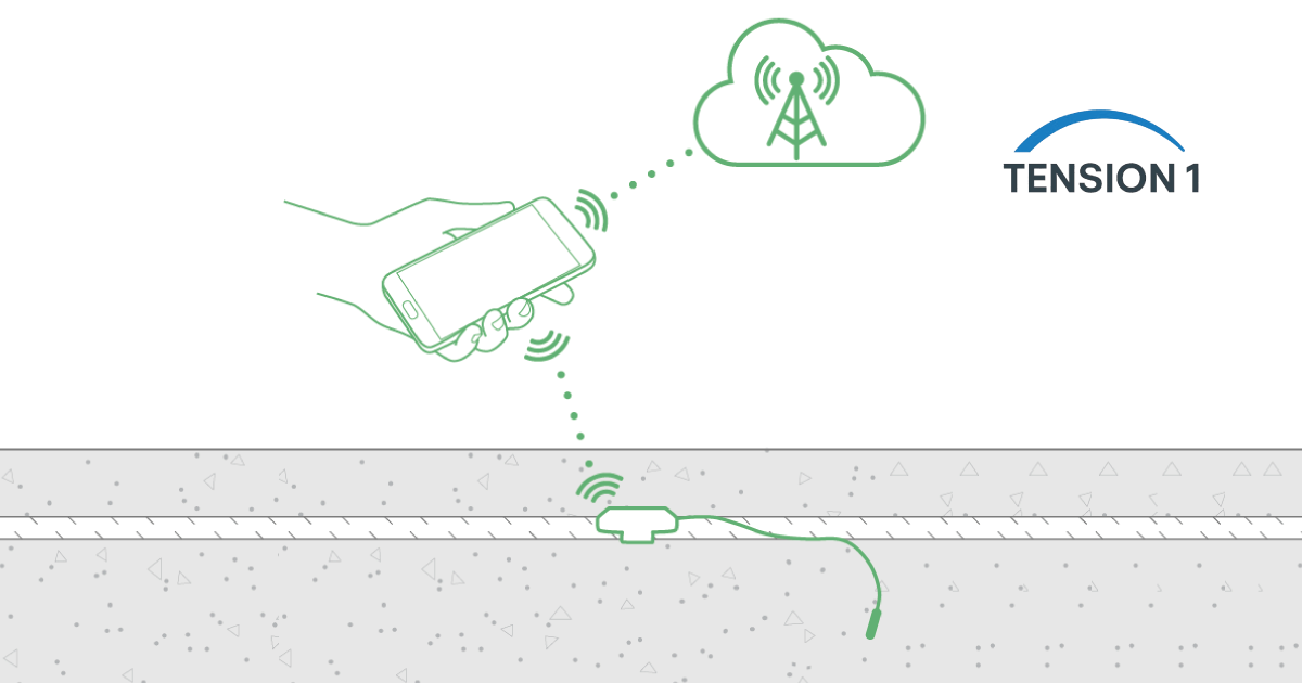
How often to inspect is covered in do post-tension slabs require regular professional inspection? On high-value or high-risk structures, continuous monitoring can supplement inspection, as described in IoT and embedded sensors for post-tension slab monitoring.
5. PT Slab vs. Conventional RC Slab: Side-by-Side Comparison
We evaluated the metrics below across multiple projects and code provisions. All values assume similar gravity loading conditions, normal-weight concrete (unit weight 145 pcf), and Grade 60 mild steel for the RC baseline.
| Criteria | Post-Tension Slab | Conventional RC Slab |
|---|---|---|
| Slab thickness | 4 to 5 in. (typical residential) | 6 to 8 in. (similar loads) |
| Concrete volume | Reduced 20 to 30% | Baseline |
| Control joint frequency | Minimal to none (PT compression) | Every 15 to 20 ft required |
| Shrinkage crack control | Active compression closes cracks | Passive (depends on steel ratio) |
| Long-span capability | Excellent (25 to 35 ft+ economical) | Limited (costly at long spans) |
| Construction timeline | Faster (fewer shores needed) | Longer (more shoring/staging) |
| Material cost | Lower net (less concrete/rebar) | Higher net for equivalent span |
| Repair complexity | Requires PT specialist | Standard rebar repair methods |
| Main design references | ACI 318-19 Ch. 8, 20, 24, 25, 26; PTI M10.2-17; PTI DC10.5-19 (on ground) | ACI 318-19 Ch. 7 (one-way) and 8 (two-way) |
Note: project-specific performance depends on design inputs, soil conditions, construction quality and the governing code edition. The values above reflect typical ranges from our field experience and published ACI and PTI guidance.
For the full structural and cost comparison, with the conditions where each system wins, see post-tension vs. reinforced concrete: when does PT win the structural battle?
6. Go Deeper: The TensionOne Post Tension Slab Library
- Foundations on clay: preventing slab movement and cracking in expansive clay soils
- Long spans: how post-tensioning prevents cracking and deflection
- Cantilevers: case study on massive PT cantilevers
- System choice: bonded vs. unbonded systems and what fails in the field
- Monitoring: embedded sensors for PT slab monitoring
- Sustainability: the embodied carbon comparison with reinforced concrete
Work with TensionOne on Your Next PT Slab Project
We built TensionOne on the principle that field experience and rigorous analysis are not in competition. Through our post-tension slab design, optimization and diagnostics services, we support general contractors, architects and engineering firms in the Dallas-Fort Worth area and beyond:
- Post-tension slab design support: tendon layouts, profile schedules, stressing calculations and detailing, prepared for the engineer of record.
- Optimization reviews: review of existing or proposed PT designs for tendon quantity, slab thickness or construction sequencing.
- PT diagnostics: technical assessment support for existing slabs showing cracking, deflection or suspected tendon distress.
- Digital tools: calculation spreadsheets and templates for PT slab design and construction verification.
Our services are independent technical support, delivered without a PE stamp. Sealing and approval remain with the licensed engineer of record. How we source and update this content is described in our editorial policy.
References: ACI 318-19, Building Code Requirements for Structural Concrete (current edition ACI CODE-318-25), American Concrete Institute. ASCE 7-22, Minimum Design Loads and Associated Criteria for Buildings and Other Structures. PTI M10.2-17, Specification for Unbonded Single Strand Tendons. PTI DC10.5-19, Standard Requirements for Design and Analysis of Shallow Post-Tensioned Concrete Foundations on Expansive and Stable Soils. ASTM A416, Standard Specification for Low-Relaxation, Seven-Wire Steel Strand for Prestressed Concrete.