Every structural engineer who works with architects on Texas projects has heard the request: extend the overhang, lose that column, open the facade. The first answer is usually a deeper concrete section or heavier steel. Both bring the same consequences: taller floor-to-floor heights, more load on the foundations, and a structural budget that starts to slip. A post tension slab changes that conversation, because it attacks the problem that actually governs cantilevers: deflection.
This case study looks at three published projects where post-tensioning made a large cantilever possible. Two are in Dallas: a residence that projects over a cliff edge, and a hospital that cantilevers 62 ft while carrying seven stories. The third is a 115 ft cantilevered walkway in the Canadian Rockies. From these projects, we draw the design and site lessons that apply to any PT cantilever.
Why Cantilevers Are a Deflection Problem Before a Strength Problem
A cantilever is fixed at one end and free at the other, and that geometry is unforgiving. Under a uniform load, the tip of a cantilever deflects wL⁴/8EI. A simply supported span of the same length deflects 5wL⁴/384EI. The ratio is 9.6: the cantilever moves almost ten times as much. Deflection also grows with the fourth power of length, so a 20 percent longer overhang deflects about twice as much.
Conventional concrete answers with depth. For one-way cantilevers, ACI 318-19 sets a minimum thickness of L/10 for nonprestressed slabs when deflections are not calculated. A 15 ft overhang would need 18 in of concrete. That depth is what eats the ceiling plenum, raises the building and loads the foundations.
What Post-Tensioning Changes
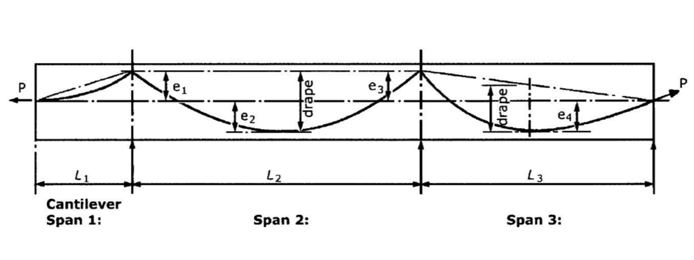
Post-tensioning adds an active force. Over the cantilever root, the tendon runs high in the section, near the top face, and its profile curves down toward the anchorage. The eccentricity between the tendon and the section centroid creates a counter-moment and an upward equivalent load that oppose the dead load. Applied before finishes go on, that upward action can hold the tip near level instead of letting it sag.
This is the load balancing method introduced by T.Y. Lin in 1963. The same principle governs long spans, as explained in how post-tensioning prevents cracking and deflection in long-span concrete structures. On a cantilever the stakes are higher, because there is no second support to share the load.
Case Study 1: Dumptop Residence, Dallas
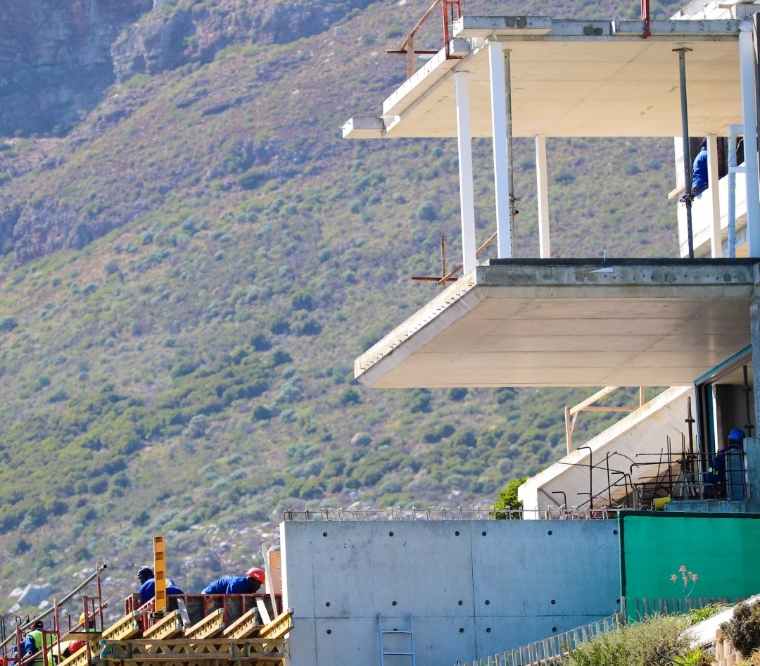
The Dumptop Residence received a 2015 PTI Award of Merit, as reported in the PTI Journal (December 2015). The house sits on top of a steep cliff in Dallas, and the architectural concept was for it to project out over the edge. According to the project write-up, post-tensioning was the only framing system with a chance of achieving that.
The governing criterion was not strength. It was the deflection of the cantilever slab edges, judged against two limits:
- Visual: edge deflections could not be noticeable to the eye.
- Facade: differential deflection between floors had to work with the glass curtain walls on the north face.
Two details from the project carry over to any cantilever. First, the deflection of the supporting slab band had to be added to the slab's own deflection, because what the facade sees is the total. Second, because the slab edges were exposed, the floor and roof slabs were kept at one thickness throughout, 13 in. Only the outer edge of the roof slab was sloped down to a 9 in edge. Uniform thickness simplified forming and gave a clean, consistent edge.
Case Study 2: Parkland Replacement Hospital, Dallas
The Parkland Replacement Hospital in Dallas received the 2015 PTI Award of Excellence in the buildings category. Its form combined a 62 ft cantilever with a 120 ft span over an opening, both carrying seven stories above. The layout gave more windows and shortened walking distances to the elevator core, which was the functional goal.
The engineers priced four systems before choosing:
- a two-story steel transfer girder, rejected because deflections were unacceptably high and the steel tonnage unrealistic;
- a seven-story steel truss with diagonals, the most cost-effective steel option;
- a cast-in-place concrete structure on two-story post-tensioned transfer girders, which raised constructability concerns about five-story shoring;
- a hybrid of concrete below and steel above, penalized by coordination between two trades in the same area.
The PT transfer girders were selected. According to the write-up, they were by far the best solution for deflection control. Post-tensioning also allowed staged stressing, which controlled floor elevations and deflections as each level was added. On a cantilever carrying a building, that ability to adjust force as load arrives is what passive reinforcement cannot offer.
Two site details are worth noting. A mockup of the most congested corner revealed that the delivered anchors were larger than the catalog units, so the wall was flared at the anchors to make room. And 88 maturity meters monitored the mass concrete placements to control internal thermal cracking. Embedded sensors of this kind are covered in our article on IoT and embedded sensors for post-tension slab monitoring.
Case Study 3: Glacier Skywalk, Alberta
The same 2015 PTI awards recognized the Glacier Skywalk in Jasper National Park. It is a glass-floored observation platform that cantilevers 35 m (115 ft) over a valley, 280 m (918 ft) above the valley floor. The structure is weathering steel, not a slab, but the principle is identical. Two multistrand tendons follow a parabolic curve to provide the uplift that balances the overturning moment, and the tendons were grouted afterward for corrosion protection.
Stressing had to be coordinated with many survey points, because no adjustment was possible once the crane released the frame. The lesson for slabs is direct. On a cantilever, the tendon force sets the final geometry, so stressing and survey belong in the same plan.
Design Lessons from These Projects
Set the Deflection Criteria from the Architecture
Both Dallas projects defined their limits from what the architecture could tolerate: edges that looked straight, and curtain walls that could absorb the movement between floors. ACI 318-19 Table 24.2.2 gives minimum limits, such as L/480 for deflection after attachment of elements likely to be damaged. Glass facades and exposed edges often need tighter project-specific criteria. Agree on them with the architect and the facade engineer before sizing anything.
Design the Back Span with the Cantilever
A cantilever's root moment has to be resisted by the adjacent span. That back span needs enough stiffness and enough tendon force to hold the root without uplift or excessive rotation. Its deflection adds to the tip movement, as the Dumptop team recorded.
Check the Root Zone for Congestion
The cantilever root is the most congested zone in the slab. Top bars, banded tendons at maximum eccentricity and, often, column reinforcement all compete for the same depth. A tendon and rebar interference section at the root, drawn at full scale in the shop drawings, catches conflicts before the pour. Parkland went further and built a mockup.
Detail the Free Edge for Torsion
Where the cantilever ends at an exposed edge carrying a facade, the edge sees torsion from the eccentric load. ACI 318-19 Section 22.7 governs torsion design, and closed stirrups are required once torsion exceeds the threshold. When the edge beam is kept thin for appearance, model it explicitly rather than treating it as a line load. Its torsional stiffness changes how much load goes back to the columns.
Check Vibration and Long-Term Movement
Long, slender cantilevers in open-plan or hospitality spaces can be lively underfoot. ACI 318 does not include a vibration check. Footfall methods such as The Concrete Centre's CCIP-016 (2006) guide are commonly used for concrete floors. Long-term deflection also deserves more than the simplified ACI multiplier on a cantilever. Creep and shrinkage models such as those in ACI 209R give a better estimate where tip movement is critical.
Post-Tensioned vs. Reinforced Concrete for Cantilevers
| Parameter | Reinforced Concrete | Post-Tensioned |
|---|---|---|
| Minimum thickness, one-way cantilever slab (ACI 318-19, deflection not calculated) | L/10 | Set by calculated deflection and stress checks |
| Deflection control | Depth and cracked-section stiffness | Active upward force from the tendon profile |
| Crack control at the root | Passive: rebar works after cracking | Precompression delays cracking |
| Adjustment during construction | None after the pour | Staged stressing can control geometry |
| Dead load on supports | Higher (deeper section) | Lower (thinner section) |
| Main construction risk | Long-term creep deflection | Shoring removal before stressing, root congestion |
A thinner cantilever also means less concrete and steel. The carbon side of that difference is covered in post tension slab vs. reinforced concrete: the embodied carbon comparison. The structural and cost comparison is in post-tension vs. reinforced concrete: when PT wins.
What Goes Wrong on Site
- Late MEP penetrations at the root: a sleeve added after the tendon shop drawings are issued can land in the tendon band at the root. A coordination round with all trades before the pour, ideally in a shared model, prevents a costly re-profile.
- Shoring removed too early: a PT cantilever only carries itself after stressing, and only once the concrete has reached the strength specified for stressing. The engineer of record should issue a written stripping sequence that ties shoring removal to strength and stressing.
- Free edge details missing: torsion reinforcement at the exposed edge is often absent from preliminary drawings and surfaces only at permit review.
- Elongations not reconciled: on a cantilever, a tendon that falls short of its force shows up directly as tip deflection. ACI 318 requires the cause to be found when measured and calculated elongations differ by more than 7 percent.
Bonded or Unbonded Tendons for Cantilevers?
In Texas buildings, unbonded monostrand dominates elevated slabs, cantilevers included. Bonded tendons offer one real advantage at a cantilever. If a strand breaks, it re-anchors in the grout and the rest of the tendon keeps its force, and that matters on an element with no alternative load path. The cost and grouting quality demands usually keep bonded systems for transfer girders and special structures.
Unbonded cantilevers perform well when three conditions are met. First, minimum bonded reinforcement is provided as ACI 318-19 requires. Second, the anchorages are fully protected, with an encapsulated system to PTI M10.2-17 at exposed edges. Third, the tendon layout avoids sharp curvature at the root. Durability and failure modes for both systems are compared in bonded vs. unbonded post tension slab systems.
Cantilevers are not only an elevated-slab question. Perimeter beams of slab-on-ground foundations also cantilever over soil that shrinks away from them, as explained in post-tension foundations in expansive clay soils. For the full overview of PT systems, see The Ultimate Guide to Post-Tension Slabs: Advantages, Design, and Longevity.
Working on a PT Cantilever?
Through our post-tension slab design, optimization and diagnostics services, we prepare cantilever tendon profiles, back-span balancing, deflection and stress checks, and root-zone interference sections for contractors, drafters and small engineering firms. Every assumption is stated so the package can be reviewed line by line. Sealing and approval remain with the licensed engineer of record.
This article is educational. The projects described are published case studies by other design teams, summarized from the PTI Journal. Nothing here is a design for any project or a PE-stamped opinion; the governing code edition and project documents take precedence.
References: Post-Tensioning Institute, "2015 PTI Project Awards," PTI Journal, December 2015. ACI 318-19, Building Code Requirements for Structural Concrete (current edition ACI CODE-318-25). ACI 209R, Guide for Modeling and Calculating Shrinkage and Creep in Hardened Concrete. PTI M10.2-17, Specification for Unbonded Single Strand Tendons. The Concrete Centre, CCIP-016, A Design Guide for Footfall Induced Vibration of Structures (2006).